Generator -- Installation |
| 1. INSTALL GENERATOR ASSEMBLY |
Install the bracket with the bolt.
- Torque:
- 20 N*m{204 kgf*cm, 15 ft.*lbf}
 |
Install the wire harness clamp stay with the bolt.
- Torque:
- 8.4 N*m{86 kgf*cm, 74 in.*lbf}
 |
Connect the wire harness clamp.
 |
Install the generator assembly to the cylinder block with the bolt.
- Torque:
- 20 N*m{204 kgf*cm, 15 ft.*lbf}
Install the 2 bolts.
- Torque:
- 43 N*m{438 kgf*cm, 32 ft.*lbf}
 |
Connect the generator connector to the generator assembly.
 |
Install the generator wire with the nut.
- Torque:
- 9.8 N*m{100 kgf*cm, 87 in.*lbf}
Install the terminal cap.
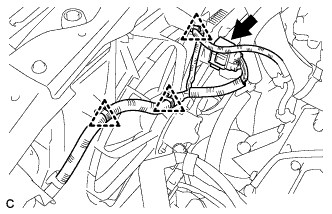
Connect the 2 wire harness clamps.
Connect the magnetic clutch connector to the compressor and magnetic clutch.
| 2. INSTALL V-RIBBED BELT |
Install the V-ribbed belt.
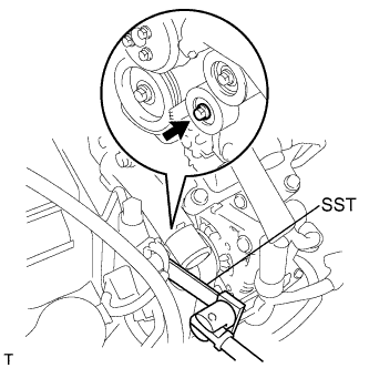 |
Using SST, turn the belt tensioner counterclockwise and remove the bar.
- SST
- 09249-63010
If it is difficult to install the V-ribbed belt, perform the following procedure:
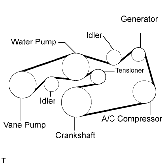
Put the V-ribbed belt on every pulley except the tensioner pulley as shown in the illustration.
While releasing the belt tension by turning the belt tensioner counterclockwise, put the V-ribbed belt on the tensioner pulley.
- NOTICE:
- Put the backside of the V-ribbed belt on the tensioner pulley and idler pulley.
- Check that the V-ribbed belt is properly set to each pulley.
After installing the V-ribbed belt, check that it fits properly in the ribbed grooves. Confirm that the belt has not slipped out of the grooves on the bottom of the crank pulley by hand.
 |
| 3. INSTALL RADIATOR ASSEMBLY |
Install the radiator to the body.
 |
Install the condenser assembly with the 4 bolts.
- Torque:
- 5.0 N*m{51 kgf*cm, 44 in.*lbf}
 |
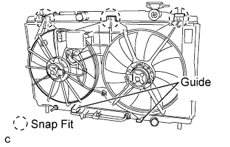
| 4. INSTALL FAN SHROUD |
Install the fan assembly with motor to the radiator with the 2 guides at the bottom and 3 snap fits on the top.
 |
Connect the fan motor connector.
 |
| 5. INSTALL RADIATOR SUPPORT UPPER |
Install the radiator support upper with the 5 bolts.
- Torque:
- 7.0 N*m{71 kgf*cm, 62 in.*lbf}
 |
Install the hood lock assembly to the radiator support upper with the 3 bolts.
- Torque:
- 7.5 N*m{77 kgf*cm, 66 in.*lbf}
 |
For LHD:
Install the hood lock control cable assembly to the radiator support upper with the clamp.
 |
For RHD:
Install the hood lock control cable assembly to the radiator support upper with the clamp.
 |
Connect the 2 horn connectors.
| 6. CONNECT NO. 1 OIL COOLER OUTLET TUBE |
Connect the No. 1 oil cooler outlet tube to the radiator assembly.
 |
| 7. CONNECT NO. 1 OIL COOLER INLET TUBE |
Connect the No. 1 oil cooler inlet tube to the radiator assembly.
 |
| 8. CONNECT RADIATOR OUTLET HOSE |
Connect the radiator hose outlet to the radiator assembly.
 |
| 9. CONNECT RADIATOR INLET HOSE |
Connect the radiator hose inlet to the radiator assembly.
 |
| 10. CONNECT RADIATOR RESERVE TANK HOSE |
Connect the radiator reservoir tank hose to the radiator assembly.
 |
| 11. INSTALL FRONT BUMPER ENERGY ABSORBER |
Install the front bumper energy absorber to the front bumper reinforcement sub-assembly.
 |
| 12. INSTALL FRONT BUMPER ASSEMBLY (w/o Headlight Cleaner System) |
Connect 2 fog light connectors.
w/ TOYOTA Parking Assist-sensor System:
Connect the clearance sonar connector and engage the clamp.
Engage each claw.
Install the front bumper assembly with the 8 screws, 2 clips, 2 radiator grille protectors and bolt.
 |
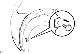
Install the pin hold clip.
- HINT:
- Use the same procedure for the RH side and LH side.
 |
| 13. INSTALL FRONT BUMPER ASSEMBLY (w/ Headlight Cleaner System) |
Connect the headlight cleaner washer hose.
 |
Connect 2 fog light connectors.
w/ TOYOTA Parking Assist-sensor System:
Connect the clearance sonar connector and engage the clamp.
Engage each claw.
Install the front bumper assembly with the 8 screws, 2 clips, 2 radiator grille protectors and bolt.
 |
Install the pin hold clip.
- HINT:
- Use the same procedure for the RH side and LH side.
|
| 14. INSTALL NO. 1 AIR CLEANER INLET |
Install the No. 1 air cleaner inlet with the bolt.
- Torque:
- 5.0 N*m{51 kgf*cm, 44 in.*lbf}
 |
| 15. INSTALL AIR CLEANER CAP SUB-ASSEMBLY |
Install the air cleaner cap sub-assembly, and connect the 3 bands.
 |
Connect the mass air flow meter connector (*1).
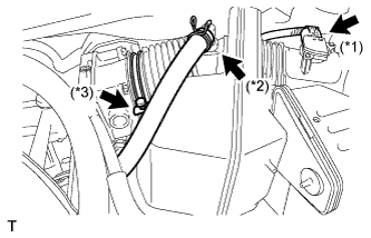 |
Connect the No. 2 ventilation hose (*2).
Connect the hose band (*3).
Connect the 3 vacuum hoses.
 |
| 16. INSTALL AIR CLEANER INLET ASSEMBLY |
Install the air cleaner inlet with the clamp and 2 bolts.
- Torque:
- 5.0 N*m{51 kgf*cm, 44 in.*lbf}
 |
| 17. CONNECT CABLE TO NEGATIVE BATTERY TERMINAL |
- Torque:
- 6.9 N*m{70 kgf*cm, 61 in.*lbf}
| 18. ADD ENGINE COOLANT |
Close the radiator drain cock plug and 2 cylinder block drain cock plugs.
- Torque:
- 13 N*m{130 kgf*cm, 9 ft.*lbf} for cylinder block drain cock plug
Slowly fill the radiator with TOYOTA Super Long Life Coolant (SLLC).
- Specified capacity:
- 9.0 liters (9.5 US qts, 7.9 lmp. qts)
- HINT:
- TOYOTA vehicles are filled with TOYOTA SLLC at the factory. In order to avoid damage to the engine cooling system and other technical problems, only use TOYOTA SLLC or similar high quality ethylene glycol based non-silicate, non-amine, non-nitrite, non-borate coolant with long-life hybrid organic acid technology (coolant with long-life hybrid organic acid technology consists of a combination of low phosphates and organic acids).
- Contact your TOYOTA dealer for further details.
Slowly pour coolant into the radiator reservoir tank until it reaches the FULL line.
Press the inlet and outlet radiator hoses several times by hand, and then check the level of the coolant.
If the coolant level is low, add coolant.
Install the radiator cap sub-assembly and reservoir tank cap.
Start the engine, and warm it up.
- HINT:
- Adjust the air conditioner set temperature to MAX (HOT).
Stop the engine, and wait until the engine coolant cools down.
Add engine coolant to the FULL line on the radiator reservoir.
| 19. CHECK FOR ENGINE COOLANT LEAKS |
- CAUTION:
- Do not remove the radiator cap while the engine and radiator are still hot. Pressurized, hot engine coolant and steam may be released and cause serious burns.
- NOTICE:
- Before performing each inspection, turn the A/C switch OFF.
Fill the radiator with coolant and attach a radiator cap tester.
 |
Warm up the engine.
Using a radiator cap tester, increase the pressure inside the radiator to 118 kPa (1.2 kgf*cm, 17 psi), and check that the pressure does not drop.
If the pressure drops, check the hoses, radiator and water pump for leaks. If no external leaks are found, check the heater core, cylinder block and cylinder head.
| 20. INSTALL V-BANK COVER SUB-ASSEMBLY |
Engage the 3 retainers to install the V-bank cover.
 |
| 21. INSTALL COOL AIR INTAKE DUCT SEAL |
Install the intake duct seal with the 7 clips.
 |
| 22. INSTALL ENGINE UNDER COVER RH |
| 23. INSTALL ENGINE UNDER COVER LH |
| 24. INSTALL FRONT FENDER APRON SEAL RH |
| 25. INSTALL FRONT WHEEL RH |
- Torque:
- 103 N*m{1,050 kgf*cm, 76 ft.*lbf}