Dtc B2272 Ignition 1 Monitor Malfunction
DESCRIPTION
WIRING DIAGRAM
INSPECTION PROCEDURE
READ VALUE USING INTELLIGENT TESTER
CHECK ENGINE SWITCH CONDITION
INSPECT RELAY (IG1 RELAY)
CHECK WIRE HARNESS (INSTRUMENT PANEL J/B - MAIN BODY ECU)
CHECK WIRE HARNESS (INSTRUMENT PANEL J/B - BATTERY AND BODY GROUND)
INSPECT INSTRUMENT PANEL J/B
DTC B2272 Ignition 1 Monitor Malfunction |
DESCRIPTION
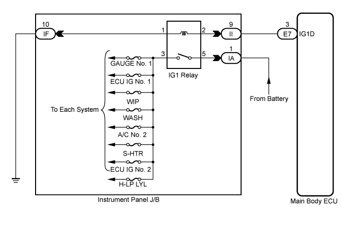
This DTC is output when there is a problem in the IG1D output circuit, which is from the inside of the main body ECU to the IG1 relay.- HINT:
- When the main body ECU is replaced with a new one and the negative (-) battery terminal is connected, the power source mode becomes the IG-ON mode. When the battery is removed and reinstalled, the power source mode that was selected when the battery was removed is restored.
- After the main body ECU is replaced, perform the registration procedures for the engine immobiliser system.
DTC No.
| DTC Detection Condition
| Trouble Area
|
B2272
| IG1 relay actuation circuit inside main body ECU or other related circuit is malfunctioning
| - Main body ECU
- IG1 relay
- Wire harness or connector
|
WIRING DIAGRAM
INSPECTION PROCEDURE
| 1.READ VALUE USING INTELLIGENT TESTER |
Connect the intelligent tester to the DLC3.
Turn the engine switch on (IG).
Turn the intelligent tester on.
Enter the following menus: Body / Body / Data List.
Read the Data List according to the display on the intelligent tester.
- HINT:
- When using the intelligent tester with the engine switch off, turn on and off any of the door courtesy light switches repeatedly at 1.5 second intervals or less until communication between the tester and vehicle starts.
Body:Tester Display
| Measurement Item/Range
| Normal Condition
| Diagnostic Note
|
IG1 Relay Mon 1
| Status of IG1 relay monitor (outer) / ON or OFF
| ON: Engine switch on (IG) (IG1 relay is ON)
OFF: Engine switch off (IG1 relay is OFF)
| -
|
- OK:
- "ON" (engine switch on (IG)) appears on the screen.
| 2.CHECK ENGINE SWITCH CONDITION |
Check the power source mode change.
When the key is inside the vehicle and the shift lever is in the P position, check that pressing the engine switch causes the power source mode to change as follows:
- OK:
- off → on (ACC) → on (IG) → off
- HINT:
- If power mode does not change to ON (IG and ACC) (CAMRY_ACV40 RM0000020S903IX.html).
- If power mode does not change to ON (IG) (CAMRY_ACV40 RM0000020SA027X.html).
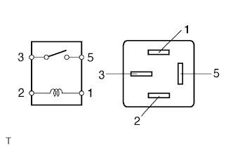
| 3.INSPECT RELAY (IG1 RELAY) |
Remove the IG1 relay from the instrument panel J/B.
Measure the resistance according to the value(s) in the table below.
- Standard Resistance:
Tester Connection
| Condition
| Specified Condition
|
3 - 5
| When battery voltage is not applied terminals 1 and 2
| 10 kΩ or higher
|
3 - 5
| When battery voltage is applied terminals 1 and 2
| Below 1 Ω
|
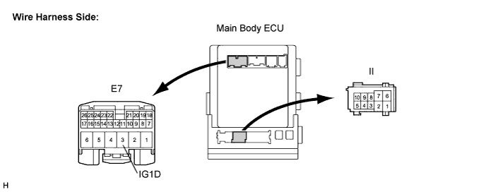
| 4.CHECK WIRE HARNESS (INSTRUMENT PANEL J/B - MAIN BODY ECU) |
Disconnect the Il J/B connector.
Disconnect the E7 ECU connector.
Measure the resistance according to the value(s) in the table below.
- Standard Resistance:
Tester Connection
| Condition
| Specified Condition
|
II-9 - E7-3 (IG1D)
| Always
| Below 1 Ω
|
E7-3 (IG1D) - Body ground
| Always
| 10 kΩ or higher
|
| | REPAIR OR REPLACE HARNESS OR CONNECTOR |
|
|
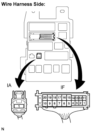
| 5.CHECK WIRE HARNESS (INSTRUMENT PANEL J/B - BATTERY AND BODY GROUND) |
Disconnect the IF and IA J/B connectors.
Measure the resistance according to the value(s) in the table below.
- Standard Resistance:
Tester Connection
| Condition
| Specified value
|
IF-10 - Body ground
| Always
| Below 1 Ω
|
Measure the voltage according to the value(s) in the table below.
- Standard Voltage:
Tester Connection
| Condition
| Specified value
|
IA-1 - Body ground
| Always
| 11 to 14 V
|
| | REPAIR OR REPLACE HARNESS OR CONNECTOR |
|
|
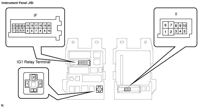
| 6.INSPECT INSTRUMENT PANEL J/B |
Measure the resistance according to the value(s) in the table below.
- Standard Resistance:
Tester Connection
| Condition
| Specified value
|
IF-10 - IG1 relay terminal-1
| Always
| Below 1 Ω
|
Il-9 - IG1 relay terminal-2
| Always
| Below 1 Ω
|
IF-10 - Body ground
| Always
| 10 kΩ or higher
|
Il-9 - Body ground
| Always
| 10 kΩ or higher
|
| | REPLACE INSTRUMENT PANEL J/B |
|
|