Dtc C0273/13 Open Or Short Circuit In Abs Motor Relay Circuit
Brake. Camry. Acv40 Gsv40
DESCRIPTION
WIRING DIAGRAM
INSPECTION PROCEDURE
INSPECT FUSIBLE LINK (ABS NO. 1 FUSE)
PERFORM ACTIVE TEST USING INTELLIGENT TESTER (ABS MOTOR RELAY)
INSPECT SKID CONTROL ECU CONNECTOR (+BM TERMINAL VOLTAGE)
INSPECT SKID CONTROL ECU CONNECTOR (GND TERMINAL CONTINUITY)
RECONFIRM DTC
DTC C0273/13 Open or Short Circuit in ABS Motor Relay Circuit |
DESCRIPTION
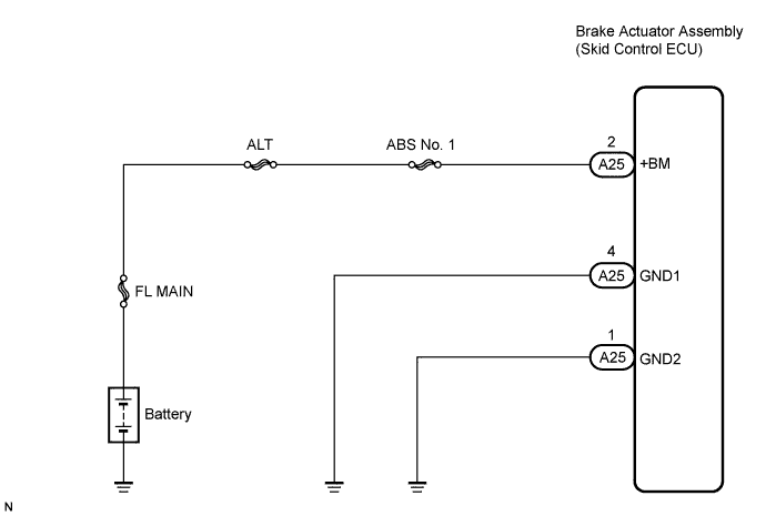
The ABS motor relay supplies power to the ABS pump motor. While the ABS is activated, the ECU turns the motor relay on and operates the ABS pump motor.If the voltage supplied to the motor relay (+BM) is below the DTCs detection threshold due to low voltage from the battery or alternator, the DTC may be stored.DTC No.
| DTC Detecting Condition
| Trouble Area
|
C0273/13
| When any of the following is detected:
- When the motor relay is actuated, voltage is not supplied to the pump motor within 0.1 second.
- When the motor relay is changed from ON to OFF, the remaining high voltage is more than 2 V for 1 second.
- For 30 to 125 msec. after the motor relay is turned from ON to OFF, the remaining high voltage is out of range. The voltage is still out of range when the motor relay is turned from ON to OFF 3 times.
| - ABS No. 1 fuse (Fusible link)
- Wire harness (+BM circuit)
- Brake actuator assembly (motor relay)
|
WIRING DIAGRAM
INSPECTION PROCEDURE
- HINT:
- When C1241/41 is output together with C0273/13, inspect and repair the trouble areas indicated by C1241/41 (CAMRY_ACV40 RM000001JD200OX.html).
- Check the condition of each related circuit connector before troubleshooting (CAMRY_ACV40 RM000000UZ301ZX.html).
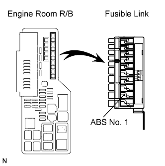
| 1.INSPECT FUSIBLE LINK (ABS NO. 1 FUSE) |
Remove the fusible link from the engine room R/B.
Check if the fusible link is melted.
- OK:
- The fusible link is not melted.
Install the fusible link to the engine room R/B with the nut.
- Torque:
- 5.4 N*m{55 kgf*cm, 48 in.*lbf}
| 2.PERFORM ACTIVE TEST USING INTELLIGENT TESTER (ABS MOTOR RELAY) |
Connect the intelligent tester to the DLC3.
Start the engine.
Select "Active Test" on the intelligent tester (CAMRY_ACV40 RM000001JBA003X.html).
Active Test: ABSTester Display
| Test Part/Control Range
| Normal Condition
|
Motor Relay
| Turns ABS motor relay ON / OFF
| Operating sound of motor is heard
|
Check the operating sound of the ABS motor relay when operating it with the intelligent tester.
- OK:
- The operating sound of the ABS motor relay should be heard.
- Result:
Result
| Proceed to
|
The operating sound is not heard
| A
|
The operating sound is heard
| B
|
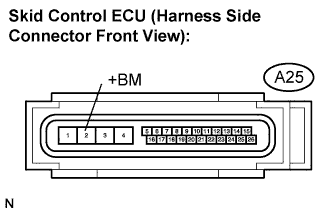
| 3.INSPECT SKID CONTROL ECU CONNECTOR (+BM TERMINAL VOLTAGE) |
Disconnect the skid control ECU connector.
Measure the voltage according to the value(s) in the table below.
- Standard voltage:
Tester Connection
| Condition
| Specified Condition
|
A25-2 (+BM) -
Body ground
| Always
| 10 to 14 V
|
| | REPAIR OR REPLACE HARNESS OR CONNECTOR (+BM CIRCUIT) |
|
|
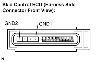
| 4.INSPECT SKID CONTROL ECU CONNECTOR (GND TERMINAL CONTINUITY) |
Measure the resistance according to the value(s) in the table below.
- Standard resistance:
Tester Connection
| Specified Condition
|
A25-4 (GND1) - Body ground
| Below 1 Ω
|
A25-1 (GND2) - Body ground
| Below 1 Ω
|
Connect the connector.
| | REPAIR OR REPLACE HARNESS OR CONNECTOR (GND CIRCUIT) |
|
|
- HINT:
- This code is detected when a problem is identified in the brake actuator assembly.
- The ABS motor relay is in the brake actuator assembly.
- Therefore, ABS motor relay inspection and motor relay unit inspection cannot be performed. Be sure to check if the DTC is output before replacing the brake actuator assembly.
Clear the DTC (CAMRY_ACV40 RM000001JB800PX.html).
Start the engine.
Drive the vehicle at a speed of 20 km/h (12 mph) or more for 30 seconds or more.
Check if the same DTC is recorded (CAMRY_ACV40 RM000001JB800PX.html).
- HINT:
- Reinstall the sensors, connectors, etc. and restore the vehicle to its prior condition before rechecking for DTCs.
- Result:
Condition
| Proceed to
|
DTC is not output
| A
|
DTC is output
| B
|
- HINT:
- If the normal system code is output (the trouble code is not output), slightly jiggle the connectors, wire harness, and fuses of the brake actuator assembly. Make sure that no DTCs are output.
- If any DTCs are output while jiggling a connector or wire harness of the brake actuator (skid control ECU), inspect and repair the connector or wire harness.
- It is suspected that the DTCs were output due to a bad connection of the connector terminal.