Dtc C1237/37 Speed Sensor Rotor Faulty
Brake. Camry. Acv40 Gsv40
DESCRIPTION
WIRING DIAGRAM
INSPECTION PROCEDURE
CHECK TIRES
INSPECT SPEED SENSOR AND SENSOR ROTOR SERRATIONS
RECONFIRM DTC
CHECK SPEED SENSOR ROTOR
CHECK SPEED SENSOR TIP
INSPECT EACH SPEED SENSOR
CHECK HARNESS AND CONNECTOR (SKID CONTROL ECU TO EACH SPEED SENSOR)
RECONFIRM DTC
DTC C1237/37 Speed Sensor Rotor Faulty |
DESCRIPTION
The skid control ECU measures the speed of each wheel by receiving signals from the speed sensor.These signals are used for recognizing that all 4 wheels are operating properly.Therefore, all wheel signals must be equal.DTC No.
| DTC Detecting Condition
| Trouble Area
|
C1237/37
| When any of the following is detected:
- Wheel speed difference between the wheels.
- Wheel sensor signal failure.
- ABS control continues for 60 sec. or more.
| - Brake actuator assembly (skid control ECU)
- Speed sensor rotor (Front)
- Rear axle hub and bearing assembly
- Speed sensor
- Speed sensor circuit
- Tire and wheel size
- Tire deformation
|
WIRING DIAGRAM
INSPECTION PROCEDURE
- HINT:
- Check the condition of each related circuit connector before troubleshooting (CAMRY_ACV40 RM000000UZ301ZX.html).
Check the size and condition of all 4 tires (CAMRY_ACV40 RM000000X9A01NX_01_0001.html).
- HINT:
- This DTC is output when tire deformation or a difference in tire size is detected.
- OK:
- The diameters of all 4 tires and air pressure are the same.
| | REPLACE TIRES SO THAT ALL 4 TIRES ARE THE SAME SIZE |
|
|
| 2.INSPECT SPEED SENSOR AND SENSOR ROTOR SERRATIONS |
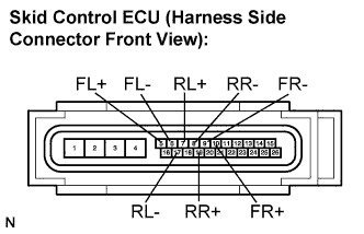
Disconnect the skid control ECU connector.
Connect the oscilloscope to each speed sensor terminal of the skid control ECU connector.
- Terminals:
Connector
| Circuit
|
A25-5 (FL+) - A25-6 (FL-)
| Front left speed sensor
|
A25-10 (FR+) - A25-9 (FR-)
| Front right speed sensor
|
A25-7 (RL+) - A25-17 (RL-)
| Rear left speed sensor
|
A25-19 (RR+) - A25-8 (RR-)
| Rear right speed sensor
|
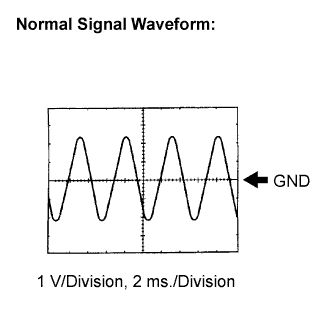
Check that a waveform is output when the tires are rotated (by the sensor circuit).
- OK:
- A waveform as shown in the figure should be output.
- HINT:
- Each sensor circuit outputs the same waveform without noise.
- As vehicle speed (wheel rotation speed) increases, the width of the waveform narrows and the output voltage becomes greater.
- When noise is identified in the waveform on the oscilloscope, the erratic signals are generated due to rotor scratches, looseness or foreign matter attached to the speed sensor.
Make sure that the waveform does not change while jiggling a connector or a wire harness.
- OK:
- The waveform does not change.
- HINT:
- If the waveform changes while jiggling a connector or a wire harness, there may be a malfunction in the connector or the wire harness.
Connect the connector.
Clear the DTC (CAMRY_ACV40 RM000001JB800HX.html).
Start the engine.
Drive the vehicle at a speed of 32 km/h (20 mph) or more for 60 seconds or more.
Check if the same DTC is recorded (CAMRY_ACV40 RM000001JB800HX.html).
- HINT:
- Reinstall the sensors, connectors, etc. and restore the vehicle to its prior condition before rechecking for DTCs.
- Result:
Condition
| Proceed to
|
DTC is not output
| A
|
DTC is output
| B
|
| 4.CHECK SPEED SENSOR ROTOR |
Check the speed sensor rotor.
Front Speed Sensor Rotor: (CAMRY_ACV40 RM000001JBG00GX.html)
Rear Speed Sensor Rotor: (CAMRY_ACV40 RM000001JDB00GX.html)
- OK:
- No scratches or foreign matter on the rotors.
- NOTICE:
- Check the speed sensor signal after the cleaning/replacement (CAMRY_ACV40 RM000001JBD011X.html).
| | CLEAN OR REPLACE SPEED SENSOR ROTOR |
|
|
Remove each speed sensor.
Check the speed sensor tip.
- OK:
- No scratches or foreign matter on the sensor tip.
- NOTICE:
- Check the speed sensor signal after the cleaning/replacement (CAMRY_ACV40 RM000001JBD011X.html).
Install the speed sensor.
| | CLEAN OR REPLACE SPEED SENSOR |
|
|
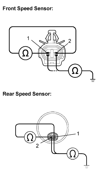
| 6.INSPECT EACH SPEED SENSOR |
Disconnect each speed sensor connector.
Measure the resistance according to the value(s) in the table below.
- Standard resistance:
- FRONT:
Tester Connection
| Condition
| Specified Condition
|
A14-1 (FL+) - A14-2 (FL-)
| Always
| 1.4 to 1.8 kΩ at 20°C (68°F)
|
A14-1 (FL+) - Body ground
| Always
| 10 kΩ or higher
|
A14-2 (FL-) - Body ground
| Always
| 10 kΩ or higher
|
A35-1 (FR+) - A35-2 (FR-)
| Always
| 1.4 to 1.8 kΩ at 20°C (68°F)
|
A35-1 (FR+) - Body ground
| Always
| 10 kΩ or higher
|
A35-2 (FR-) - Body ground
| Always
| 10 kΩ or higher
|
- REAR:
Tester Connection
| Condition
| Specified Condition
|
g1-1 (RL+) - g1-2 (RL-)
| Always
| Below 2.2 kΩ
|
g1-1 (RL+) - Body ground
| Always
| 10 kΩ or higher
|
g1-2 (RL-) - Body ground
| Always
| 10 kΩ or higher
|
f1-1 (RR+) - f1-2 (RR-)
| Always
| Below 2.2 kΩ
|
f1-1 (RR+) - Body ground
| Always
| 10 kΩ or higher
|
f1-2 (RR-) - Body ground
| Always
| 10 kΩ or higher
|
Connect the connector.
- NOTICE:
- Check the speed sensor signal after replacement (CAMRY_ACV40 RM000001JBD011X.html).
| | REPLACE EACH SPEED SENSOR |
|
|
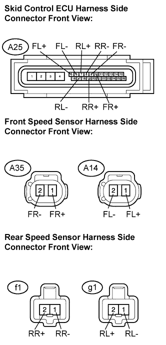
| 7.CHECK HARNESS AND CONNECTOR (SKID CONTROL ECU TO EACH SPEED SENSOR) |
Disconnect the skid control ECU connector.
Measure the resistance according to the value(s) in the table below.
- Standard resistance:
- FRONT:
Tester Connection
| Condition
| Specified Condition
|
A25-5 (FL+) - A14-1 (FL+)
| Always
| Below 1 Ω
|
A25-6 (FL-) - A14-2 (FL-)
| Always
| Below 1 Ω
|
A25-10 (FR+) - A35-1 (FR+)
| Always
| Below 1 Ω
|
A25-9 (FR-) - A35-2 (FR-)
| Always
| Below 1 Ω
|
A25-5 (FL+) - Body ground
| Always
| 10 kΩ or higher
|
A25-6 (FL-) - Body ground
| Always
| 10 kΩ or higher
|
A25-10 (FR+) - Body ground
| Always
| 10 kΩ or higher
|
A25-9 (FR-) - Body ground
| Always
| 10 kΩ or higher
|
- REAR:
Tester Connection
| Condition
| Specified Condition
|
A25-7 (RL+) - g1-1 (RL+)
| Always
| Below 1 Ω
|
A25-17 (RL-) - g1-2 (RL-)
| Always
| Below 1 Ω
|
A25-19 (RR+) - f1-1 (RR+)
| Always
| Below 1 Ω
|
A25-8 (RR-) - f1-2 (RR-)
| Always
| Below 1 Ω
|
A25-7 (RL+) - Body ground
| Always
| 10 kΩ or higher
|
A25-17 (RL-) - Body ground
| Always
| 10 kΩ or higher
|
A25-19 (RR+) - Body ground
| Always
| 10 kΩ or higher
|
A25-8 (RR-) - Body ground
| Always
| 10 kΩ or higher
|
Connect the connector.
| | REPAIR OR REPLACE HARNESS OR CONNECTOR (SKID CONTROL ECU TO EACH SPEED SENSOR) |
|
|
Clear the DTC (CAMRY_ACV40 RM000001JB800HX.html).
Start the engine.
Drive the vehicle at the speed of 32 km/h (20 mph) or more for at least 60 seconds.
Check if the same DTC is recorded (CAMRY_ACV40 RM000001JB800HX.html).
- HINT:
- Reinstall the sensors, connectors, etc. and restore the vehicle to its prior condition before rechecking for DTCs.
- Result:
Condition
| Proceed to
|
DTC (C1237/37) is not output
| A
|
DTC (C1237/37) is output
| B
|