Engine Immobiliser System (W/ Entry And Start System) Security Indicator Light Circuit
DESCRIPTION
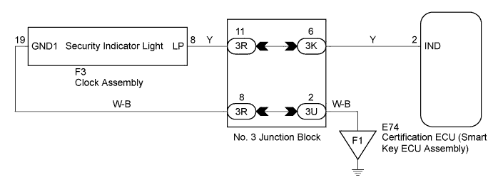
WIRING DIAGRAM
INSPECTION PROCEDURE
PERFORM ACTIVE TEST USING INTELLIGENT TESTER
CHECK HARNESS AND CONNECTOR (CERTIFICATION ECU - CLOCK ASSEMBLY)
CHECK HARNESS AND CONNECTOR (CLOCK ASSEMBLY - BODY GROUND)
ENGINE IMMOBILISER SYSTEM (w/ Entry and Start System) - Security Indicator Light Circuit |
DESCRIPTION
The security indicator light blinks continuously due to a continuous signal received from the certification ECU (smart key ECU assembly) while the engine immobiliser is set.
WIRING DIAGRAM
INSPECTION PROCEDURE
- NOTICE:
- If the certification ECU (smart key ECU assembly) is replaced, register all the keys.
| 1.PERFORM ACTIVE TEST USING INTELLIGENT TESTER |
Connect the intelligent tester to the DLC3.
Turn the engine switch on (IG).
Turn the intelligent tester on.
Enter the following menus: Body / Entry & Start / Active Test.
Perform the Active Test according to the display on the intelligent tester.
Entry & Start (Certification ECU (Smart Key ECU Assembly))Tester Display
| Test Part
| Control Range
| Diagnostic Note
|
Security Indicator
| Security indicator light
| ON or OFF
| -
|
- OK:
- The security indicator light turns on and off according to the intelligent tester operation.
| OK |
|
|
|
| REPLACE CERTIFICATION ECU (SMART KEY ECU ASSEMBLY) |
|
| 2.CHECK HARNESS AND CONNECTOR (CERTIFICATION ECU - CLOCK ASSEMBLY) |
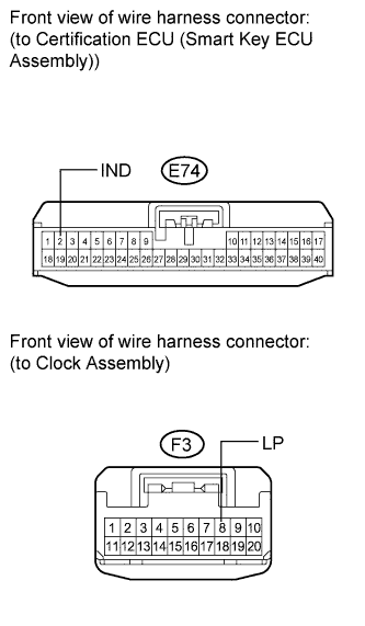
Disconnect the certification ECU (smart key ECU assembly) connector.
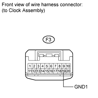
Disconnect the clock assembly connector.
Measure the resistance according to the value(s) in the table below.
- Standard Resistance:
Tester Connection
| Condition
| Specified Condition
|
E74-2 (IND) - F3-8 (LP)
| Always
| Below 1 Ω
|
E74-2 (IND) - Body ground
| Always
| 10 kΩ or higher
|
| | REPAIR OR REPLACE HARNESS OR CONNECTOR |
|
|
| 3.CHECK HARNESS AND CONNECTOR (CLOCK ASSEMBLY - BODY GROUND) |
Measure the resistance according to the value(s) in the table below.
- Standard Resistance:
Tester Connection
| Condition
| Specified Condition
|
F3-19 (GND1) - Body ground
| Always
| Below 1 Ω
|
| | REPAIR OR REPLACE HARNESS OR CONNECTOR |
|
|