Lighting System Headlight (Hi-Beam) Circuit
DESCRIPTION
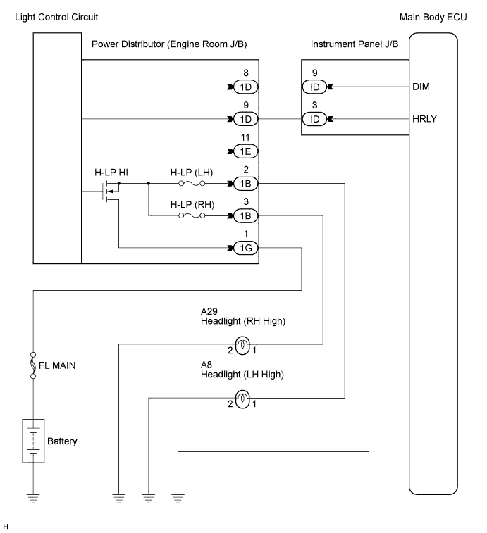
WIRING DIAGRAM
INSPECTION PROCEDURE
PERFORM ACTIVE TEST USING INTELLIGENT TESTER
INSPECT INSTRUMENT PANEL JUNCTION BLOCK ASSEMBLY
CHECK HARNESS AND CONNECTOR (ENGINE ROOM J/B ASSEMBLY - BATTERY AND BODY GROUND)
INSPECT ENGINE ROOM JUNCTION BLOCK ASSEMBLY
CHECK HARNESS AND CONNECTOR (ENGINE ROOM J/B ASSEMBLY - INSTRUMENT PANEL J/B ASSEMBLY)
CHECK HARNESS AND CONNECTOR (SHORT IN RELAY-DRIVEN CIRCUIT)
INSPECT ENGINE ROOM JUNCTION BLOCK ASSEMBLY
LIGHTING SYSTEM - Headlight (HI-BEAM) Circuit |
DESCRIPTION
When the low beam headlights are on, and the dimmer switch is turned to the HIGH position, the main body ECU turns the high beam headlights on.- HINT:
- When a short circuit occurs between the power distributor and high beam headlight, the power distributor stops the high beam headlight relay operation (Fail-safe function).
- The high beam headlight relay is built into the power distributor, so unlike conventional relays, it cannot be removed for inspection.
WIRING DIAGRAM
INSPECTION PROCEDURE
| 1.PERFORM ACTIVE TEST USING INTELLIGENT TESTER |
Connect the intelligent tester to the DLC3.
Turn the ignition switch to the ON position and turn the intelligent tester main switch on.
Select the item below in the ACTIVE TEST and then check that the relay operates.
Main Body (Main Body ECU):Item
| Test Details
| Diagnostic Note
|
Head Light Hi
| High beam headlights ON / OFF
| -
|
- OK:
- High beam headlight relay operates. (High beam headlights illuminate.)
| | PROCEED TO NEXT CIRCUIT INSPECTION SHOWN IN PROBLEM SYMPTOMS TABLE |
|
|
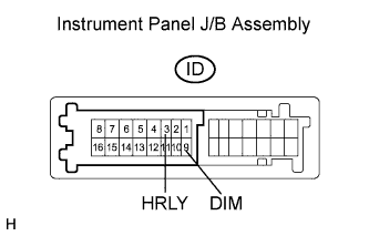
| 2.INSPECT INSTRUMENT PANEL JUNCTION BLOCK ASSEMBLY |
Measure the voltage according to the value(s) in the table below.
- Standard voltage:
Tester Connection
| Condition
| Specified Condition
|
ID-3 (HRLY) - Body ground
| Light control switch OFF → HEAD
| 10 to 14 V → Below 1 V
|
ID-9 (DIM) - Body ground
| Light control switch in HEAD and dimmer switch LOW → HIGH
| 10 to 14 V → Below 1 V
|
| 3.CHECK HARNESS AND CONNECTOR (ENGINE ROOM J/B ASSEMBLY - BATTERY AND BODY GROUND) |
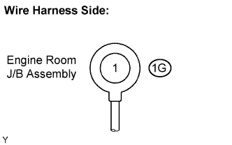
Disconnect the 1G engine room J/B assembly connector.
Measure the voltage according to the value(s) in the table below.
- Standard voltage:
Tester Connection
| Condition
| Specified Condition
|
1G-1 - Body ground
| Always
| 10 to 14 V
|
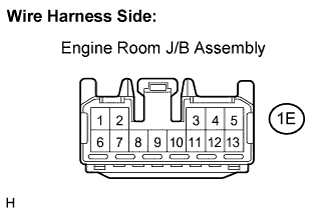
Disconnect the 1E engine room J/B assembly connector.
Measure the resistance according to the value(s) in the table below.
- Standard resistance:
Tester Connection
| Condition
| Specified Condition
|
1E-11 - Body ground
| Always
| Below 1 Ω
|
| | REPAIR OR REPLACE HARNESS OR CONNECTOR |
|
|
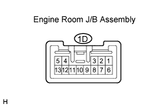
| 4.INSPECT ENGINE ROOM JUNCTION BLOCK ASSEMBLY |
Reconnect the 1G and 1E engine room J/B assembly connectors.
Disconnect the 1D engine room J/B assembly connector.
Measure the voltage according to the value(s) in the table below.
- Standard voltage:
Tester Connection
| Condition
| Specified Condition
|
1D-8 - Body ground
| Always
| 10 to 14 V
|
1D-9 - Body ground
| Always
| 10 to 14 V
|
| | REPLACE ENGINE ROOM JUNCTION BLOCK ASSEMBLY (POWER DISTRIBUTOR) |
|
|
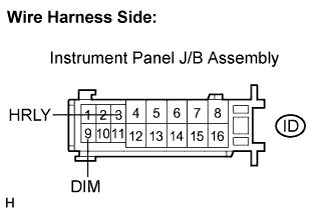
| 5.CHECK HARNESS AND CONNECTOR (ENGINE ROOM J/B ASSEMBLY - INSTRUMENT PANEL J/B ASSEMBLY) |
Reconnect the 1D engine room J/B assembly connector.
Disconnect the ID instrument panel J/B connector.
Measure the voltage according to the value(s) in the table below.
- Standard voltage:
Tester Connection
| Condition
| Specified Condition
|
ID-3 (HRLY) - Body ground
| Always
| 10 to 14 V
|
ID-9 (DIM) - Body ground
| Always
| 10 to 14 V
|
| | REPAIR OR REPLACE HARNESS OR CONNECTOR |
|
|
| OK |
|
|
|
| REPLACE INSTRUMENT PANEL JUNCTION BLOCK ASSEMBLY |
|
| 6.CHECK HARNESS AND CONNECTOR (SHORT IN RELAY-DRIVEN CIRCUIT) |
Remove the H-LP (RH) fuse from the engine room J/B assembly.
Turn the light control switch to the HEAD position.
Turn the dimmer switch to the HIGH position.
Check if the high beam headlight LH illuminates.
Turn the dimmer switch to the LOW position.
Install the H-LP (RH) fuse and remove the H-LP (LH) fuse.
Turn the dimmer switch to the HIGH position.
Check if the high beam headlight RH illuminates.
- OK:
- Either high beam headlight LH or RH illuminates.
| | REPAIR OR REPLACE HARNESS OR CONNECTOR (SHORT CIRCUIT BETWEEN FUSE AND BULB) |
|
|
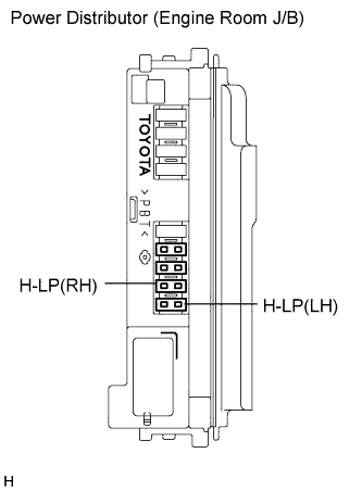
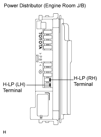
| 7.INSPECT ENGINE ROOM JUNCTION BLOCK ASSEMBLY |
Remove the H-LP (RH) fuse and H-LP (LH) fuse from the engine room J/B assembly.
Measure the voltage between the loading slot of each fuse and body ground.
- Standard voltage:
Tester Connection
| Condition
| Specified Condition
|
H-LP (RH) Terminal - Body ground
| Light control switch in HEAD and dimmer switch in HIGH
| 10 to 14 V
|
H-LP (LH) Terminal - Body ground
| Light control switch in HEAD and dimmer switch in HIGH
| 10 to 14 V
|
| | REPLACE ENGINE ROOM JUNCTION BLOCK ASSEMBLY (POWER DISTRIBUTOR) |
|
|
| OK |
|
|
|
| REPAIR OR REPLACE HARNESS OR CONNECTOR (OPEN CIRCUIT BETWEEN FUSE AND BODY GROUND) |
|