Airbag System Diagnosis Circuit
DESCRIPTION
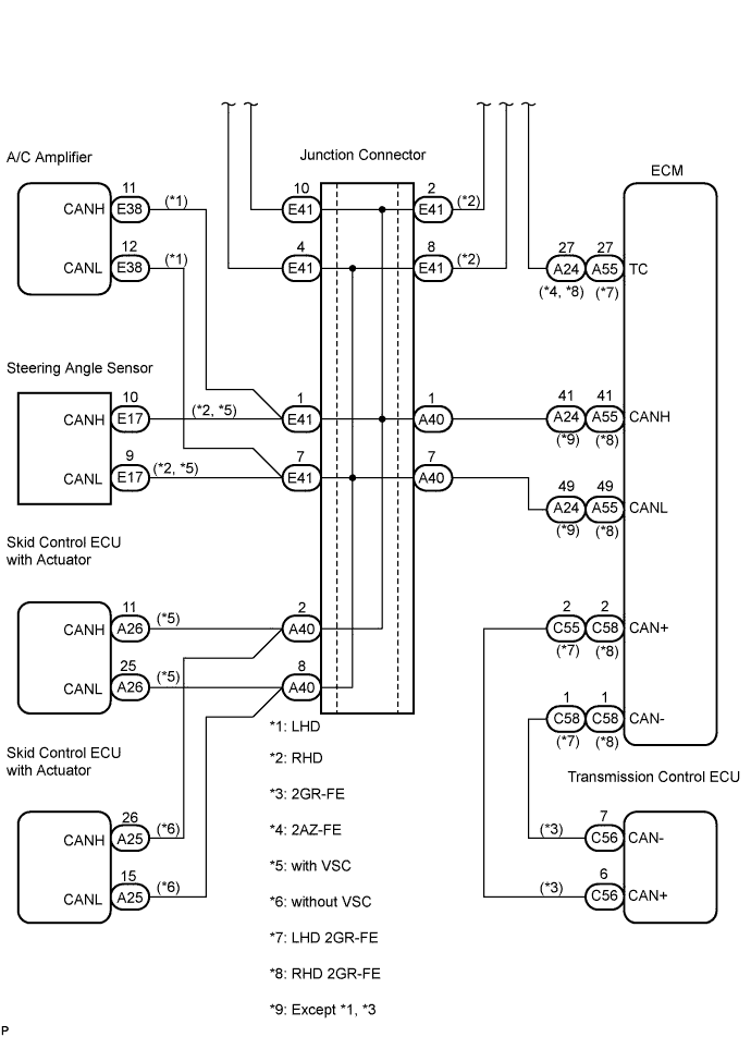
WIRING DIAGRAM
INSPECTION PROCEDURE
CHECK CAN COMMUNICATION SYSTEM
CHECK WIRE HARNESS (DLC3 - ECM)
CHECK WIRE HARNESS (CG OF DLC3 - BODY GROUND)
CHECK WIRE HARNESS (TC OF ECM - BODY GROUND)
AIRBAG SYSTEM - Diagnosis Circuit |
DESCRIPTION
DTC output mode is set by connecting terminals TC and CG of the DLC3.DTCs are displayed by blinking of the SRS warning light.- HINT:
- When each warning light stays blinking, a ground short in the wiring of terminal TC of the DLC3 or an internal ground short in each ECU is suspected.
- A DTC output mode signal is transmitted through CAN communication system to each ECU including the center airbag sensor assembly. Thus when all systems do not enter DTC output mode, there may be an ECM malfunction.
WIRING DIAGRAM
INSPECTION PROCEDURE
| 1.CHECK CAN COMMUNICATION SYSTEM |
Check if a CAN communication system DTC is output (CAMRY_ACV40 RM000000WIB00WX.htmlfor LHD, CAMRY_ACV40 RM000000WIB00YX.html for RHD).
- Result:
Condition
| Proceed to
|
DTC is not output
| A
|
DTC is output
| B
|
| | REPAIR CIRCUITS INDICATED BY OUTPUT DTCS |
|
|
| 2.CHECK WIRE HARNESS (DLC3 - ECM) |
Turn the ignition switch to the LOCK position.
Disconnect the connector from the ECM.
Measure the resistance according to the value(s) in the table below.
- Standard resistance:
- for 2GR-FE (LHD):
Tester Connection
| Condition
| Specified Condition
|
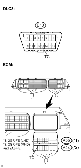
E10-13 (TC) - A55-27 (TC)
| Always
| Below 1 Ω
|
- for 2GR-FE (RHD) and for 2AZ-FE:
Tester Connection
| Condition
| Specified Condition
|
E10-13 (TC) - A24-27 (TC)
| Always
| Below 1 Ω
|
| | REPAIR OR REPLACE WIRE HARNESS (TC OF DLC3 - TC OF ECM) |
|
|
| 3.CHECK WIRE HARNESS (CG OF DLC3 - BODY GROUND) |
Measure the resistance according to the value(s) in the table below.
- Standard resistance:
Tester Connection
| Condition
| Specified Condition
|
E10-4 (CG) - Body ground
| Always
| Below 1 Ω
|
| | REPAIR OR REPLACE WIRE HARNESS (CG OF DLC3 - BODY GROUND) |
|
|
| 4.CHECK WIRE HARNESS (TC OF ECM - BODY GROUND) |
Measure the resistance according to the value(s) in the table below.
- Standard resistance:
- for 2GR-FE (LHD):
Tester Connection
| Condition
| Specified Condition
|
A55-27 (TC) - Body ground
| Always
| 1 MΩ or higher
|
- for 2GR-FE (RHD) and for 2AZ-FE:
Tester Connection
| Condition
| Specified Condition
|
A24-27 (TC) - Body ground
| Always
| 1 MΩ or higher
|
| | REPAIR OR REPLACE WIRE HARNESS OR EACH ECU |
|
|