Audio And Visual System Steering Pad Switch Circuit
DESCRIPTION
WIRING DIAGRAM
INSPECTION PROCEDURE
INSPECT RADIO RECEIVER
INSPECT STEERING PAD SWITCH ASSEMBLY
INSPECT SPIRAL CABLE
AUDIO AND VISUAL SYSTEM - Steering Pad Switch Circuit |
DESCRIPTION
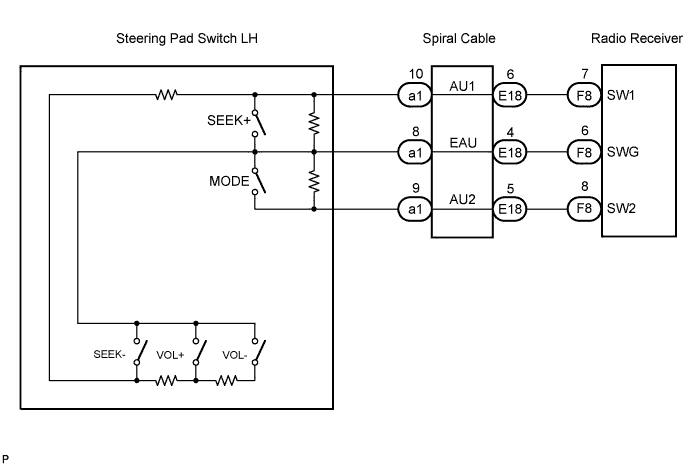
This circuit sends an operation signal from the steering pad switch to the radio receiver.If there is an open in the circuit, the audio system cannot be operated using the steering pad switch.If there is a short in the circuit, the same condition as that when the switch is continuously depressed occurs.Therefore, the radio receiver cannot be operated using the steering pad switch, and also the radio receiver itself cannot function.
WIRING DIAGRAM
INSPECTION PROCEDURE
- NOTICE:
- The vehicle is equipped with an SRS (Supplemental Restraint System) which includes components such as airbags. Before servicing (including removal or installation of parts), be sure to read the precautionary notice for the Supplemental Restraint System (CAMRY_ACV40 RM000000KT1016X.html).
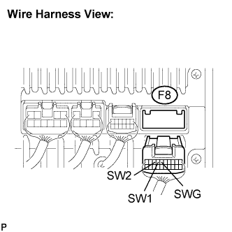
Disconnect the radio receiver connector F8.
Measure the resistance according to the value(s) in the table below.
- Standard resistance:
Tester connection
| Condition
| Specified condition
|
SW1 - SWG
| No switch is pushed
| Approx. 100 kΩ
|
SW1 - SWG
| SEEK+ switch: push
| 0 to 2.5 Ω
|
SW1 - SWG
| SEEK- switch: push
| Approx. 0.3 kΩ
|
SW1 - SWG
| VOL+ switch: push
| Approx. 1 kΩ
|
SW1 - SWG
| VOL- switch: push
| Approx. 3.1 kΩ
|
SW2 - SWG
| No switch is pushed
| Approx. 100 kΩ
|
SW2 - SWG
| MODE switch: push
| 0 to 2.5 Ω
|
| OK |
|
|
|
| PROCEED TO NEXT CIRCUIT INSPECTION SHOWN IN PROBLEM SYMPTOMS TABLE |
|
| 2.INSPECT STEERING PAD SWITCH ASSEMBLY |
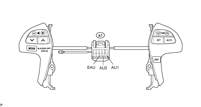
Disconnect the steering pad switch assembly connector.
Measure the resistance according to the values in the table below.
- Standard resistance:
Tester connection
| Condition
| Specified condition
|
AU1 - EAU
| No switch is pushed
| Approx. 100 kΩ
|
AU1 - EAU
| SEEK+ switch: push
| 0 to 2.5 Ω
|
AU1 - EAU
| SEEK- switch: push
| Approx. 0.3 kΩ
|
AU1 - EAU
| VOL+ switch: push
| Approx. 1 kΩ
|
AU1 - EAU
| VOL- switch: push
| Approx. 3.1 kΩ
|
AU2 - EAU
| No switch is pushed
| Approx. 100 kΩ
|
AU2 - EAU
| MODE switch: push
| 0 to 2.5 Ω
|
| | REPLACE STEERING PAD SWITCH ASSEMBLY |
|
|
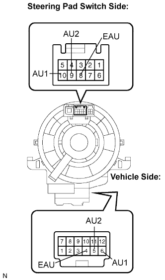
Disconnect the steering pad switch and spiral cable connectors.
Measure the resistance according to the value(s) in the table below.
- Standard resistance:
Tester connection
| Spiral Cable Position
| Specified condition
|
EAU - EAU
| Center
| Below 1 Ω
|
2.5 rotations to the left
|
2.5 rotations to the right
|
AU1 - AU1
| Center
| Below 1 Ω
|
2.5 rotations to the left
|
2.5 rotations to the right
|
AU2 - AU2
| Center
| Below 1 Ω
|
2.5 rotations to the left
|
2.5 rotations to the right
|
- NOTICE:
- The spiral cable is an important part of the SRS airbag system. Incorrect removal or installation of the spiral cable may prevent the airbag from deploying. Be sure to read the pages shown in the brackets below.
- HINT:
- Removal (CAMRY_ACV40 RM000000UWD00RX.html)
- Installation (CAMRY_ACV40 RM000000UWA00QX.html)
| OK |
|
|
|
| REPAIR OR REPLACE HARNESS OR CONNECTOR (SPIRAL CABLE - RADIO RECEIVER) |
|