Power Door Lock Control System Rear Door Lock Motor Rh Circuit
DESCRIPTION
WIRING DIAGRAM
INSPECTION PROCEDURE
INSPECT REAR DOOR LOCK ASSEMBLY
CHECK WIRE HARNESS (REAR DOOR LOCK - MAIN BODY ECU (INSTRUMENT PANEL J/B))
POWER DOOR LOCK CONTROL SYSTEM - Rear Door Lock Motor RH Circuit |
DESCRIPTION
The rear right door lock motor is built into the rear right door lock assembly.The main body ECU controls the rear right door lock motor to lock/unlock the rear right door. This ECU applies current from terminal ACT+ to terminal ACT- to operate the motor to lock the door. It reverses the direction of the current flow to operate the motor to unlock the door.
WIRING DIAGRAM
INSPECTION PROCEDURE
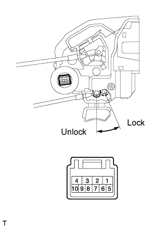
| 1.INSPECT REAR DOOR LOCK ASSEMBLY |
Remove the rear door lock assembly RH.
Apply battery voltage and check operation of the door lock motor.
- OK:
Measurement Condition
| Specified Condition
|
Battery positive (+) → Terminal 4
Battery negative (-) → Terminal 1
| Lock
|
Battery positive (+) → Terminal 1
Battery negative (-) → Terminal 4
| Unlock
|
| | REPLACE REAR DOOR LOCK ASSEMBLY |
|
|
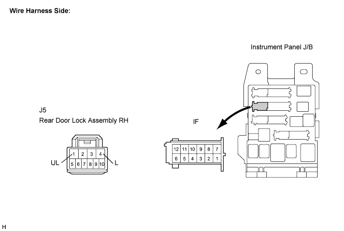
| 2.CHECK WIRE HARNESS (REAR DOOR LOCK - MAIN BODY ECU (INSTRUMENT PANEL J/B)) |
Disconnect the rear door lock assembly RH connector.
Disconnect the ECU (instrument panel J/B) connector.
Measure the resistance according to the value(s) in the table below.
- Standard resistance:
Tester Connection
(Symbols)
| Condition
| Specified Condition
|
J5-4 (L) - IF-5
| Always
| Below 1 Ω
|
J5-1 (UL) - IF-18
| Always
| Below 1 Ω
|
IF-5 - Body ground
| Always
| 10 kΩ or higher
|
IF-18 - Body ground
| Always
| 10 kΩ or higher
|
| | REPAIR OR REPLACE HARNESS OR CONNECTOR |
|
|
| OK |
|
|
|
| PROCEED TO NEXT CIRCUIT INSPECTION SHOWN IN PROBLEM SYMPTOMS TABLE |
|