Power Door Lock Control System Rear Door Unlock Detection Switch Lh Circuit
DESCRIPTION
WIRING DIAGRAM
INSPECTION PROCEDURE
SYSTEM CHECK
READ VALUE USING INTELLIGENT TESTER (UNLOCK DETECTION SWITCH)
INSPECT REAR DOOR LOCK ASSEMBLY (UNLOCK DETECTION SWITCH)
CHECK WIRE HARNESS (REAR DOOR LOCK ASSEMBLY - MAIN BODY ECU)
POWER DOOR LOCK CONTROL SYSTEM - Rear Door UNLOCK Detection Switch LH Circuit |
DESCRIPTION
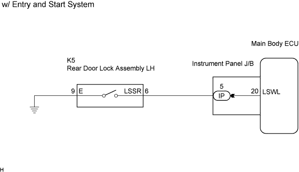
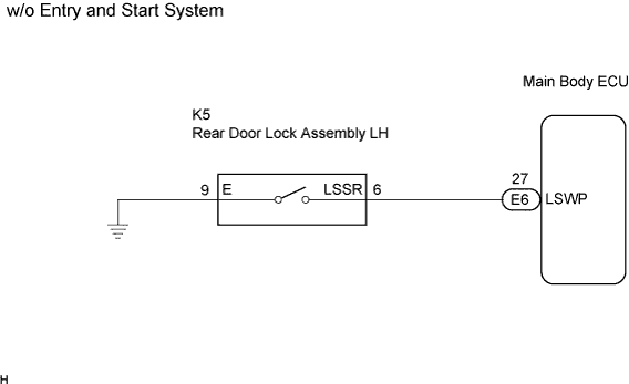
The rear left door unlock detection switch is built into the rear left door lock assembly. The switch turns on when the rear left door is locked and turns off when the door is unlocked.
WIRING DIAGRAM
INSPECTION PROCEDURE
Check the vehicle specification.
- Result:
Result
| Proceed to
|
w/ Entry and Start System
| A
|
w/o Entry and Start System
| B
|
| 2.READ VALUE USING INTELLIGENT TESTER (UNLOCK DETECTION SWITCH) |
Connect intelligent tester to the DLC3.
Turn the ignition switch on (IG).
Turn the tester on.
Enter the following menus: Body / Main Body / Data List.
Read the Data List according to the display on the tester.
Main Body:Tester Display
| Measurement Item / Range
| Normal Condition
| Diagnostic Note
|
RL-Door Lock Pos SW
| Rear left door lock position switch signal / ON or OFF
| ON: Rear left door is unlocked
OFF: Rear left door is locked
| -
|
- OK:
- The display is as specified in the normal condition column.
| OK |
|
|
|
| PROCEED TO NEXT CIRCUIT INSPECTION SHOWN IN PROBLEM SYMPTOMS TABLE |
|
| 3.INSPECT REAR DOOR LOCK ASSEMBLY (UNLOCK DETECTION SWITCH) |
Remove the rear door lock assembly LH.
Measure the resistance according to the value(s) in the table below.
- Standard resistance:
Tester Connection
| Measurement Condition
| Door Lock Condition
| Specified Condition
|
6 - 9
| Battery positive (+) → Terminal 4
Battery negative (-) → Terminal 1
| Lock
| 10 kΩ or higher
|
6 - 9
| Battery positive (+) → Terminal 1
Battery negative (-) → Terminal 4
| Unlock
| Below 1 Ω
|
| | REPLACE REAR DOOR LOCK ASSEMBLY |
|
|
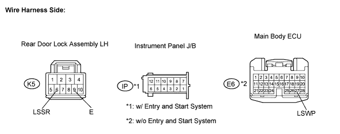
| 4.CHECK WIRE HARNESS (REAR DOOR LOCK ASSEMBLY - MAIN BODY ECU) |
Disconnect the rear door lock assembly LH connector.
Disconnect the junction block*1 or ECU*2 connector.
- *1: w/ Entry and Start System
- *2: w/o Entry and Start System
Measure the resistance according to the value(s) in the table below.
- Standard resistance:
Tester Connection
(Symbols)
| Condition
| Specified Condition
|
K5-6 (LSSR) - IP-5*1
| Always
| Below 1 Ω
|
K5-6 (LSSR) - E6-27 (LSWP)*2
| Always
| Below 1 Ω
|
K5-6 (LSSR) - Body ground
| Always
| 10 kΩ or higher
|
K5-9 (E) - Body ground
| Always
| Below 1 Ω
|
- *1: w/ Entry and Start System
- *2: w/o Entry and Start System
- Result:
Result
| Proceed to
|
OK (w/ Entry and Start System)
| A
|
OK (w/o Entry and Start System)
| B
|
NG
| C
|
| | PROCEED TO NEXT CIRCUIT INSPECTION SHOWN IN PROBLEM SYMPTOMS TABLE |
|
|
| | REPAIR OR REPLACE HARNESS OR CONNECTOR |
|
|
| A |
|
|
|
| REPLACE MAIN BODY ECU (INSTRUMENT PANEL J/B) |
|