Dtc P0571 Brake Switch A Circuit
DESCRIPTION
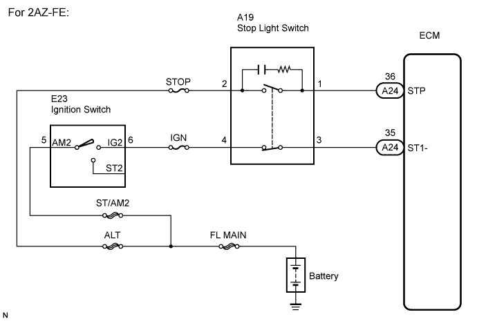
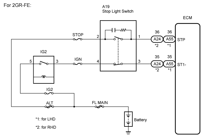
WIRING DIAGRAM
INSPECTION PROCEDURE
READ VALUE ON INTELLIGENT TESTER
CHECK HARNESS AND CONNECTOR (STOP LIGHT SWITCH - BATTERY)
INSPECT STOP LIGHT SWITCH
CHECK ECM
DTC P0571 Brake Switch "A" Circuit |
DESCRIPTION
When the brake pedal is depressed, the stop light switch sends a signal to the ECM. When the ECM receives this signal, it cancels the cruise control. The fail-safe function operates to enable normal driving even if there is a malfunction in the stop light signal circuit. The cancellation condition occurs when voltage is applied to terminal STP. When the brake is applied, voltage is normally applied to terminal STP of the ECM through the STOP fuse and the stop light switch, and the ECM turns the cruise control off.DTC No.
| DTC Detection Condition
| Trouble Area
|
P0571
| When voltage of STP terminal and that of ST1- terminal of ECM are less than 1 V for 0.5 sec. or more
| - Stop light switch
- Stop light switch circuit
- ECM
|
WIRING DIAGRAM
INSPECTION PROCEDURE
- HINT:
- Inspect the fuses for circuits related to this system before performing the following inspection procedure.
| 1.READ VALUE ON INTELLIGENT TESTER |
Connect the intelligent tester to the DLC3.
Turn the ignition switch to ON, and turn the intelligent tester main switch on.
Check the DATA LIST for proper functioning of the stop light switch.
ECM (Cruise control):Item
| Measurement Item / Display (Range)
| Normal Condition
| Diagnostic Note
|
Stop Light SW M-CPU
| Stop light switch signal (Main CPU) / ON or OFF
| ON: Brake pedal depressed
OFF: Brake pedal released
| -
|
- OK:
- When the brake pedal is operated, the display changes as shown above.
- Result:
Result
| Proceed to
|
NG
| A
|
OK (for 2AZ-FE)
| B
|
OK (for 2GR-FE)
| C
|
| 2.CHECK HARNESS AND CONNECTOR (STOP LIGHT SWITCH - BATTERY) |
Disconnect the stop light switch connector.
Measure the voltage according to the value(s) in the table below.
- Standard voltage:
Tester Connection
| Condition
| Specified Condition
|
A19-2 - Body ground
| Always
| 10 to 14 V
|
A19-4 - Body ground
| Ignition switch on (IG)
| 10 to 14 V
|
| | REPAIR OR REPLACE HARNESS OR CONNECTOR |
|
|
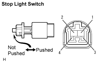
| 3.INSPECT STOP LIGHT SWITCH |
Remove the stop light switch (CAMRY_ACV40 RM0000022KA00UX.html).
Measure the resistance according to the value(s) in the table below.
- Standard resistance:
Tester Connection
| Switch Condition
| Specified Condition
|
1 - 2
| Switch pin not pushed
| Below 1 Ω
|
3 - 4
| Switch pin not pushed
| 10 kΩ or higher
|
1 - 2
| Switch pin pushed
| 10 kΩ or higher
|
3 - 4
| Switch pin pushed
| Below 1 Ω
|
Install the stop light switch (CAMRY_ACV40 RM0000022K800UX.html).
Reconnect the stop light switch connector.
Disconnect the ECM connector.
Turn the ignition switch to ON.
Measure the voltage according to the value(s) in the table below.
- Standard voltage (for 2GR-FE (LHD)):
Tester Connection
| Brake Pedal Condition
| Specified Condition
|
A55-36 (STP) - Body ground
| Depressed
| 10 to 14 V
|
A55-36 (STP) - Body ground
| Released
| Below 1 V
|
A55-35 (ST1-) - Body ground
| Depressed
| Below 1 V
|
A55-35 (ST1-) - Body ground
| Released
| 10 to 14 V
|
- Standard voltage (2AZ-FE, 2GR-FE (RHD)):
Tester Connection
| Brake Pedal Condition
| Specified Condition
|
A24-36 (STP) - Body ground
| Depressed
| 10 to 14 V
|
A24-36 (STP) - Body ground
| Released
| Below 1 V
|
A24-35 (ST1-) - Body ground
| Depressed
| Below 1 V
|
A24-35 (ST1-) - Body ground
| Released
| 10 to 14 V
|
- Result:
Result
| Proceed to
|
NG
| A
|
OK (for 2AZ-FE)
| B
|
OK (for 2GR-FE)
| C
|
| A |
|
|
|
| REPAIR OR REPLACE HARNESS OR CONNECTOR (STOP LIGHT SWITCH - ECM) |
|