Dtc C1241/41 Low Battery Positive Voltage
Brake. Camry. Acv40 Gsv40
DESCRIPTION
WIRING DIAGRAM
INSPECTION PROCEDURE
INSPECT ECU-IG NO. 2 FUSE
CHECK BATTERY
INSPECT SKID CONTROL ECU (IG1 TERMINAL)
INSPECT SKID CONTROL ECU (GND TERMINAL)
RECONFIRM DTC
DTC C1241/41 Low Battery Positive Voltage |
DESCRIPTION
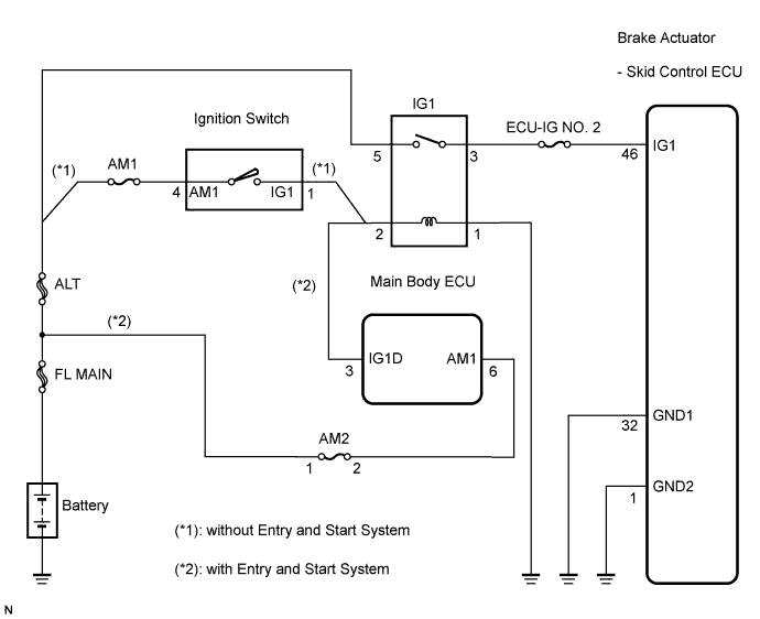
If a malfunction is detected in the power supply circuit, the skid control ECU (housed in the actuator assembly) stores this DTC and the fail safe function prohibits ABS operation.This DTC is stored when the IG1 terminal voltage deviates from the DTC detection condition due to a malfunction in the power supply or charging circuit such as the battery or alternator circuit, etc.The DTC is cancelled when the IG1 terminal voltage returns to normal.DTC No.
| DTC Detection Condition
| Trouble Area
|
C1241/41
| When any of the following is detected:
- At a vehicle speed of 2 mph (3 km/h) or more, the IG1 terminal voltage is 9.5 V or less for 10 seconds or more.
- When the solenoid relay remains ON and the IG1 terminal voltage is 9.5 V or less, the relay contact is open for 0.2 seconds or more.
- While the VSC NO. 1 (fail safe) relay is ON after VSC NO. 2 relay ON, the IG1 terminal voltage is 9.5 V or less and the actuator pump drive motor is OFF for 0.1 second or more.
| - ECU-IG NO. 2 fuse
- Battery
- Charging system
- Power source circuit
- Internal power supply circuit of the skid control ECU
|
WIRING DIAGRAM
INSPECTION PROCEDURE
- NOTICE:
- When replacing the brake actuator assembly, perform zero point calibration (CAMRY_ACV40 RM000000XHR05BX.html).
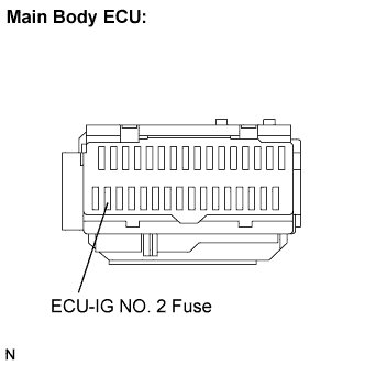
| 1.INSPECT ECU-IG NO. 2 FUSE |
Remove the ECU-IG NO. 2 fuse from the main body ECU.
Measure the resistance according to the value(s) in the table below.
- Standard resistance:
Tester Connection
| Condition
| Specified Condition
|
ECU-IG NO. 2 (7.5 A) fuse
| Always
| Below 1 Ω
|
| | REPLACE ECU-IG NO. 2 FUSE |
|
|
Install the ECU-IG NO. 2 fuse.
Check the battery voltage.
- Standard voltage:
- 10 to 14 V
| | CHECK AND REPLACE CHARGING SYSTEM OR BATTERY |
|
|
| 3.INSPECT SKID CONTROL ECU (IG1 TERMINAL) |
Disconnect the skid control ECU connector.
Turn the ignition switch on (IG).
Measure the voltage according to the value(s) in the table below.
- Standard voltage:
Tester Connection
| Condition
| Specified Condition
|
A26-46 (IG1) - Body ground
| Ignition switch on (IG)
| 10 to 14 V
|
| | REPAIR OR REPLACE HARNESS OR CONNECTOR (IG1 CIRCUIT) |
|
|
| 4.INSPECT SKID CONTROL ECU (GND TERMINAL) |
Turn the ignition switch off.
Measure the resistance according to the value(s) in the table below.
- Standard resistance:
Tester Connection
| Condition
| Specified Condition
|
A26-32 (GND1) - Body ground
| Always
| Below 1 Ω
|
A26-1 (GND2) - Body ground
| Always
| Below 1 Ω
|
| | REPAIR OR REPLACE HARNESS OR CONNECTOR (GND CIRCUIT) |
|
|
Reconnect the skid control ECU connector.
Clear the DTC (CAMRY_ACV40 RM000000XHV08UX.html).
Turn the ignition switch on (IG).
Check if the same DTC is recorded (CAMRY_ACV40 RM000000XHV08UX.html).
- Result:
Condition
| Proceed to
|
DTC (C1241/41) is not output
| A
|
DTC (C1241/41) is output
| B
|
- HINT:
- If troubleshooting has been carried out according to the Problem Symptoms Table, refer back to the table and proceed to the next step (CAMRY_ACV40 RM000000XHN08DX.html).
| | REPLACE BRAKE ACTUATOR ASSEMBLY |
|
|
| A |
|
|
|
| USE SIMULATION METHOD TO CHECK |
|