DESCRIPTION
WIRING DIAGRAM
INSPECTION PROCEDURE
CHECK LUGGAGE COMPARTMENT DOOR OPEN FUNCTION
CHECK LUGGAGE COMPARTMENT DOOR LOCK CYLINDER ASSEMBLY (CANCEL CONDITION)
PERFORM ACTIVE TEST USING INTELLIGENT TESTER (LUGGAGE COMPARTMENT DOOR LOCK (MOTOR))
READ VALUE USING INTELLIGENT TESTER (LUGGAGE COMPARTMENT DOOR LOCK (COURTESY SWITCH))
INSPECT LUGGAGE COMPARTMENT DOOR LOCK CYLINDER ASSEMBLY
CHECK HARNESS AND CONNECTOR (MAIN BODY ECU - LUGGAGE COMPARTMENT DOOR LOCK CYLINDER)
CHECK HARNESS AND CONNECTOR (LUGGAGE COMPARTMENT DOOR LOCK CYLINDER - BODY GROUND)
READ VALUE USING INTELLIGENT TESTER (COURTESY SWITCH)
INSPECT LUGGAGE COMPARTMENT DOOR LOCK ASSEMBLY (MOTOR)
CHECK HARNESS AND CONNECTOR (MAIN BODY ECU - LUGGAGE COMPARTMENT DOOR LOCK)
CHECK HARNESS AND CONNECTOR (LUGGAGE COMPARTMENT DOOR LOCK - BODY GROUND)
INSPECT LUGGAGE COMPARTMENT DOOR LOCK ASSEMBLY (COURTESY SWITCH)
CHECK HARNESS AND CONNECTOR (MAIN BODY ECU - LUGGAGE COMPARTMENT DOOR LOCK)
READ VALUE USING INTELLIGENT TESTER (TRUNK OPEN MODE)
READ VALUE USING INTELLIGENT TESTER (LUGGAGE COMPARTMENT DOOR OPENER SWITCH)
CHECK WAVE ENVIRONMENT
PERFORM KEY DIAGNOSTIC MODE INSPECTION
CHECK HARNESS AND CONNECTOR (CERTIFICATION ECU - OUTSIDE ELECTRICAL KEY OSCILLATOR)
REPLACE OUTSIDE ELECTRICAL KEY OSCILLATOR (for Luggage Compartment)
CHECK OUTSIDE ELECTRICAL KEY OSCILLATOR (OPERATION)
INSPECT LUGGAGE COMPARTMENT DOOR OPENER OUTER SWITCH
CHECK HARNESS AND CONNECTOR (CERTIFICATION ECU - LUGGAGE COMPARTMENT DOOR OPENER SWITCH)
CHECK HARNESS AND CONNECTOR (LUGGAGE COMPARTMENT DOOR OPENER SWITCH - BODY GROUND)
ENTRY AND START SYSTEM - Luggage Compartment Door Entry Unlock Function does not Operate when Key is Outside Luggage Compartment |
DESCRIPTION
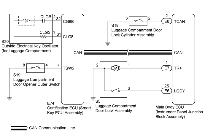
When the luggage compartment door entry unlock function does not operate, one of the following may be the cause: 1) luggage compartment door opener outer switch malfunction; 2) communication malfunction between the outside electrical key oscillator (for luggage compartment) and certification ECU (smart key ECU assembly); 3) the main body ECU (instrument panel junction block assembly) receives the luggage compartment door opener outer switch ON signal, but is unable to send the signal to the certification ECU (smart key ECU assembly) through CAN communication; or 4) certification ECU (smart key ECU assembly) malfunction.
WIRING DIAGRAM
INSPECTION PROCEDURE
- NOTICE:
- The entry and start system (for entry function) uses a multiplex communication system (LIN communication system) and CAN communication system. Inspect the communication function by following How to Proceed with Troubleshooting (CAMRY_ACV40 RM000000XU707QX.html). Troubleshoot the entry and start system (for entry function) after confirming that the communication system is functioning properly.
| 1.CHECK LUGGAGE COMPARTMENT DOOR OPEN FUNCTION |
Check that luggage compartment door open functions can be operated by using the luggage compartment door opener outer switch and electrical key transmitter.
- Result:
Result
| Proceed to
|
Both luggage compartment door opener outer switch and electrical key transmitter do not operate
| A
|
Luggage compartment door opener outer switch does not operate
| B
|
Electrical key transmitter does not operate
| C
|
| |
|
| | REPLACE ELECTRICAL KEY TRANSMITTER |
|
|
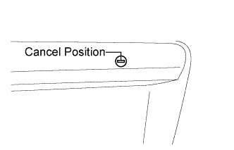
| 2.CHECK LUGGAGE COMPARTMENT DOOR LOCK CYLINDER ASSEMBLY (CANCEL CONDITION) |
Check that the luggage compartment door lock cylinder assembly is in the cancel position.
- Result:
Result
| Proceed to
|
Except cancel position
| A
|
Cancel position
| B
|
| 3.PERFORM ACTIVE TEST USING INTELLIGENT TESTER (LUGGAGE COMPARTMENT DOOR LOCK (MOTOR)) |
Connect the intelligent tester to the DLC3.
Turn the engine switch on (IG).
Turn the intelligent tester on.
Enter the following menus: Body / Main Body / Active Test.
Perform the Active Test according to the display on the intelligent tester.
Main Body (Main Body ECU (Instrument Panel Junction Block))Tester Display
| Test Part
| Control Range
| Diagnostic Note
|
Trunk and Back-door Open
| Luggage compartment door lock motor
| ON/OFF
| -
|
- OK:
- Luggage compartment door lock motor operates according to the intelligent tester operation.
| 4.READ VALUE USING INTELLIGENT TESTER (LUGGAGE COMPARTMENT DOOR LOCK (COURTESY SWITCH)) |
Enter the following menus: Body / Main Body / Data List.
Read the Data List according to the display on the intelligent tester.
Main Body (Main Body ECU (Instrument Panel Junction Block Assembly))Tester Display
| Measurement Item/Range
| Normal Condition
| Diagnostic Note
|
Luggage Courtesy SW
| Luggage compartment door courtesy light switch signal / ON or OFF
| ON: Luggage compartment door open
OFF: Luggage compartment door closed
| -
|
- OK:
- On the intelligent tester screen, the item changes between ON and OFF according to above chart.
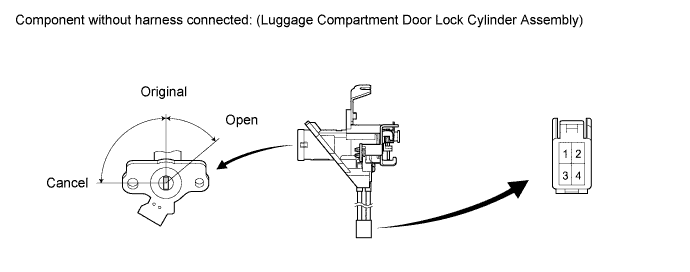
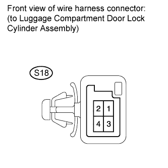
| 5.INSPECT LUGGAGE COMPARTMENT DOOR LOCK CYLINDER ASSEMBLY |
Remove the luggage compartment door lock cylinder assembly (CAMRY_ACV40 RM000001OIM01LX_01_0025.html).
Measure the resistance according to the value(s) in the table below.
- Standard Resistance:
Tester Connection
| Condition
| Specified Condition
|
1 - 3
| Open position
| Below 1 Ω
|
1 - 3
| Original position
| 10 kΩ or higher
|
2 - 3
| Original position
| 10 kΩ or higher
|
2 - 3
| Cancel position
| Below 1 Ω
|
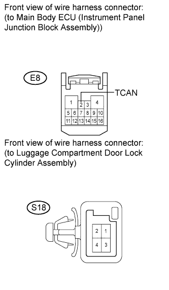
| 6.CHECK HARNESS AND CONNECTOR (MAIN BODY ECU - LUGGAGE COMPARTMENT DOOR LOCK CYLINDER) |
Disconnect the main body ECU (instrument panel junction block assembly) connector.
Measure the resistance according to the value(s) in the table below.
- Standard Resistance:
Tester Connection
| Condition
| Specified Condition
|
E8-2 (TCAN) - S18-2
| Always
| Below 1 Ω
|
E8-2 (TCAN) - Body ground
| Always
| 10 kΩ or higher
|
| | REPAIR OR REPLACE HARNESS OR CONNECTOR |
|
|
| 7.CHECK HARNESS AND CONNECTOR (LUGGAGE COMPARTMENT DOOR LOCK CYLINDER - BODY GROUND) |
Measure the resistance according to the value(s) in the table below.
- Standard Resistance:
Tester Connection
| Condition
| Specified Condition
|
S18-3 - Body ground
| Always
| Below 1 Ω
|
| | REPAIR OR REPLACE HARNESS OR CONNECTOR |
|
|
| OK |
|
|
|
| REPLACE MAIN BODY ECU (INSTRUMENT PANEL JUNCTION BLOCK ASSEMBLY) |
|
| 8.READ VALUE USING INTELLIGENT TESTER (COURTESY SWITCH) |
Enter the following menus: Body / Main Body / Data List.
Read the Data List according to the display on the intelligent tester.
Main Body (Main Body ECU (Instrument Panel Junction Block Assembly))Tester Display
| Measurement Item/Range
| Normal Condition
| Diagnostic Note
|
Luggage Courtesy SW
| Luggage compartment door courtesy light switch signal / ON or OFF
| ON: Luggage compartment door open
OFF: Luggage compartment door closed
| -
|
- OK:
- On the intelligent tester screen, the item changes between ON and OFF according to above chart.
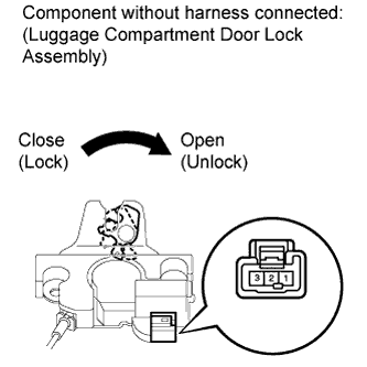
| 9.INSPECT LUGGAGE COMPARTMENT DOOR LOCK ASSEMBLY (MOTOR) |
Remove the luggage compartment door lock assembly (CAMRY_ACV40 RM000001OIQ00ZX.html).
Move the door lock to the lock position.
Apply battery voltage to the door lock motor and check the operation of the door lock motor.
- OK:
Measurement Condition
| Specified Condition
|
Battery positive (+) → Terminal 1
Battery negative (-) → Terminal 2
| Unlocks
|
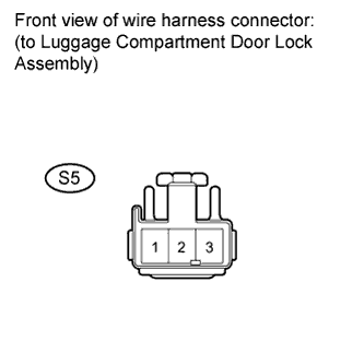
| 10.CHECK HARNESS AND CONNECTOR (MAIN BODY ECU - LUGGAGE COMPARTMENT DOOR LOCK) |
Disconnect the main body ECU (instrument panel junction block assembly) connector.
Measure the resistance according to the value(s) in the table below.
- Standard Resistance:
Tester Connection
| Condition
| Specified Condition
|
E7-1 (TR+) - S5-1
| Always
| Below 1 Ω
|
E7-1 (TR+) - Body ground
| Always
| 10 kΩ or higher
|
| | REPAIR OR REPLACE HARNESS OR CONNECTOR |
|
|
| OK |
|
|
|
| REPLACE MAIN BODY ECU (INSTRUMENT PANEL JUNCTION BLOCK ASSEMBLY) |
|
| 11.CHECK HARNESS AND CONNECTOR (LUGGAGE COMPARTMENT DOOR LOCK - BODY GROUND) |
Measure the resistance according to the value(s) in the table below.
- Standard Resistance:
Tester Connection
| Condition
| Specified Condition
|
S5-2 - Body ground
| Always
| Below 1 Ω
|
| | REPAIR OR REPLACE HARNESS OR CONNECTOR |
|
|
| 12.INSPECT LUGGAGE COMPARTMENT DOOR LOCK ASSEMBLY (COURTESY SWITCH) |
Remove the luggage compartment door lock assembly (CAMRY_ACV40 RM000001OIQ00ZX.html).
Measure the resistance according to the value(s) in the table below.
- Standard Resistance:
Tester Connection
| Condition
| Specified Condition
|
2 - 3
| Unlocked
| Below 1 Ω
|
2 - 3
| Locked
| 10 kΩ or higher
|
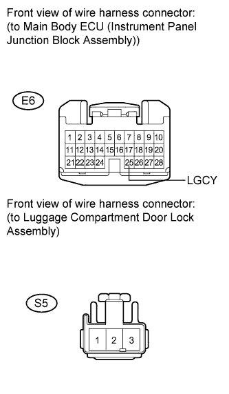
| 13.CHECK HARNESS AND CONNECTOR (MAIN BODY ECU - LUGGAGE COMPARTMENT DOOR LOCK) |
Disconnect the main body ECU (instrument panel junction block assembly) connector.
Measure the resistance according to the value(s) in the table below.
- Standard Resistance:
Tester Connection
| Condition
| Specified Condition
|
E6-25 (LGCY) - S5-3
| Always
| Below 1 Ω
|
E6-25 (LGCY) - Body ground
| Always
| 10 kΩ or higher
|
| | REPAIR OR REPLACE HARNESS OR CONNECTOR |
|
|
| OK |
|
|
|
| REPLACE MAIN BODY ECU (INSTRUMENT PANEL JUNCTION BLOCK ASSEMBLY) |
|
| 14.READ VALUE USING INTELLIGENT TESTER (TRUNK OPEN MODE) |
Connect the intelligent tester to the DLC3.
Turn the engine switch on (IG).
Turn the intelligent tester on.
Enter the following menus: Body / Entry & Start / Data List.
Read the Data List according to the display on the intelligent tester.
Entry & Start (Certification ECU (Smart Key ECU Assembly))Tester Display
| Measurement Item/Range
| Normal Condition
| Diagnostic Note
|
Trunk Open Mode
| Trunk Open Mode / ON or OFF
| Customization status displayed
| -
|
- Result:
Result
| Proceed to
|
Entry luggage open function is ON
| A
|
Entry luggage open function is OFF
| B
|
| 15.READ VALUE USING INTELLIGENT TESTER (LUGGAGE COMPARTMENT DOOR OPENER SWITCH) |
Read the Data List according to the display on the intelligent tester.
Entry & Start (Certification ECU (Smart Key ECU Assembly))Tester Display
| Measurement Item/Range
| Normal Condition
| Diagnostic Note
|
Tr/B-Door Unlock SW
| Luggage compartment door opener outer switch / ON or OFF
| ON: Luggage compartment door opener outer switch is pushed
OFF: Luggage compartment door opener outer switch is not pushed
| -
|
- OK:
- On the intelligent tester screen, the item changes between ON and OFF according to above chart.
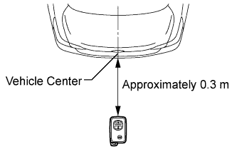
| 16.CHECK WAVE ENVIRONMENT |
Bring the electrical key transmitter near the outside electrical key oscillator (luggage compartment), and perform an entry luggage compartment open function check.
- NOTICE:
- If the key is brought within 0.2 m (0.656 ft) of the rear bumper, communication is not possible.
- HINT:
- When pressing the luggage compartment door opener outer switch, hold the electrical key transmitter about 1 m (3.28 ft.) above the ground and about 0.3 m (0.984 ft.) away from the vehicle as shown in the illustration.
- When the electrical key transmitter is brought near the electrical key antenna, the possibility of wave interference decreases, and it can be determined if wave interference is causing the problem symptom.
- If the operation is normal, the possibility of wave interference is high. Also, added vehicle components may cause wave interference. If installed, remove them and perform the operation check.
- OK:
- Entry functions operate normally.
| OK |
|
|
|
| AFFECTED BY WAVE INTERFERENCE |
|
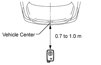
| 17.PERFORM KEY DIAGNOSTIC MODE INSPECTION |
Diagnostic mode inspection (outside electrical key oscillator (luggage compartment))
Connect the intelligent tester to the DLC3.
Turn the engine switch on (IG).
Turn the intelligent tester on.
Enter the following menus: Body / Entry & Start / Utility / Communication Check (Key Diag Mode) / Overhead + Luggage (outside).
When the electrical key transmitter is held at the same height as the rear bumper upper surface aligning it with the center of the rear of the vehicle, check that the wireless door lock buzzer sounds.
- HINT:
- Hold the electrical key transmitter at the same height as the rear bumper upper surface and align with the center of the rear of the vehicle (0.7 to 1.0 m (2.30 to 3.28 ft.)). Make sure that the direction of the key is as shown in the illustration.
- If the buzzer sounds, it can be determined that the luggage compartment exterior transmitter is operating normally.
- OK:
- Wireless door lock buzzer sounds.
| OK |
|
|
|
| REPLACE CERTIFICATION ECU (SMART KEY ECU ASSEMBLY) |
|
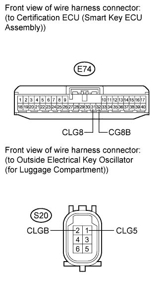
| 18.CHECK HARNESS AND CONNECTOR (CERTIFICATION ECU - OUTSIDE ELECTRICAL KEY OSCILLATOR) |
Disconnect the certification ECU (smart key ECU assembly) connector.
Disconnect the outside electrical key oscillator connector.
Measure the resistance according to the value(s) in the table below.
- Standard Resistance:
Tester Connection
| Condition
| Specified Condition
|
E74-32 (CG8B) - S20-2 (CLGB)
| Always
| Below 1 Ω
|
E74-31 (CLG8) - S20-1 (CLG5)
| Always
| Below 1 Ω
|
E74-32 (CG8B) - Body ground
| Always
| 10 kΩ or higher
|
E74-31 (CLG8) - Body ground
| Always
| 10 kΩ or higher
|
| | REPAIR OR REPLACE HARNESS OR CONNECTOR |
|
|
| 19.REPLACE OUTSIDE ELECTRICAL KEY OSCILLATOR (for Luggage Compartment) |
Replace the outside electrical key oscillator (for luggage compartment) (CAMRY_ACV40 RM000001LTW00DX.html).
| 20.CHECK OUTSIDE ELECTRICAL KEY OSCILLATOR (OPERATION) |
Check that the entry functions operate normally.
- OK:
- Entry functions operate normally.
| | REPLACE CERTIFICATION ECU (SMART KEY ECU ASSEMBLY) |
|
|
| OK |
|
|
|
| END (OUTSIDE ELECTRICAL KEY OSCILLATOR WAS DEFECTIVE) |
|
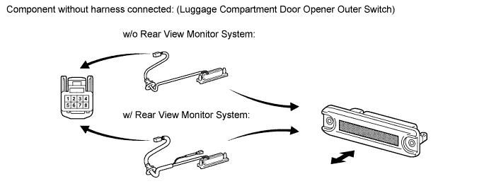
| 21.INSPECT LUGGAGE COMPARTMENT DOOR OPENER OUTER SWITCH |
Disconnect the luggage compartment door opener outer switch connector.
Measure the resistance according to the value(s) in the table below.
- Standard Resistance:
Tester Connection
| Switch Condition
| Specified Condition
|
4 - 8
| Luggage compartment door opener outer switch not pushed (OFF)
| 10 kΩ or higher
|
4 - 8
| Luggage compartment door opener outer switch pushed (ON)
| Below 1 Ω
|
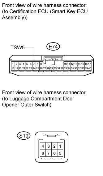
| 22.CHECK HARNESS AND CONNECTOR (CERTIFICATION ECU - LUGGAGE COMPARTMENT DOOR OPENER SWITCH) |
Disconnect the certification ECU (smart key ECU assembly) connector.
Measure the resistance according to the value(s) in the table below.
- Standard Resistance:
Tester Connection
| Condition
| Specified Condition
|
E74-7 (TSW5) - S19-4
| Always
| Below 1 Ω
|
E74-7 (TSW5) - Body ground
| Always
| 10 kΩ or higher
|
| | REPAIR OR REPLACE HARNESS OR CONNECTOR |
|
|
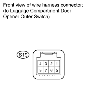
| 23.CHECK HARNESS AND CONNECTOR (LUGGAGE COMPARTMENT DOOR OPENER SWITCH - BODY GROUND) |
Measure the resistance according to the value(s) in the table below.
- Standard Resistance:
Tester Connection
| Condition
| Specified Condition
|
S19-8 - Body ground
| Always
| Below 1 Ω
|
| | REPAIR OR REPLACE HARNESS OR CONNECTOR |
|
|
| OK |
|
|
|
| REPLACE CERTIFICATION ECU (SMART KEY ECU ASSEMBLY) |
|