Anti-Lock Brake System Tc And Cg Terminal Circuit
Brake. Camry. Acv40 Gsv40
DESCRIPTION
WIRING DIAGRAM
INSPECTION PROCEDURE
CHECK CAN COMMUNICATION SYSTEM
CHECK HARNESS AND CONNECTOR (ECM TO DLC3)
CHECK HARNESS AND CONNECTOR (DLC3 CG CIRCUIT)
REPAIR OR REPLACE HARNESS OR CONNECTOR (TC TERMINAL CIRCUIT)
ANTI-LOCK BRAKE SYSTEM - TC and CG Terminal Circuit |
DESCRIPTION
DTC output mode is set by connecting terminals TC and CG of the DLC3.DTCs are indicated by the blinking pattern of the ABS warning light.
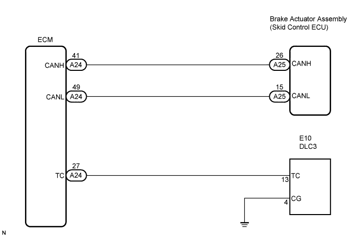
WIRING DIAGRAM
- HINT:
- When warning lights continue to blink, a ground short in the wiring of terminal TC of the DLC3 or an internal ground short in one or more ECUs is suspected.
INSPECTION PROCEDURE
- HINT:
- Check the condition of each related circuit connector before troubleshooting (CAMRY_ACV40 RM000000UZ301ZX.html).
| 1.CHECK CAN COMMUNICATION SYSTEM |
Check if a CAN communication DTC is output (CAMRY_ACV40 RM000001JB800LX.html).
- Result:
Result
| Proceed to
|
CAN communication system DTC is output
| A
|
CAN communication system DTC is not output
| B
|
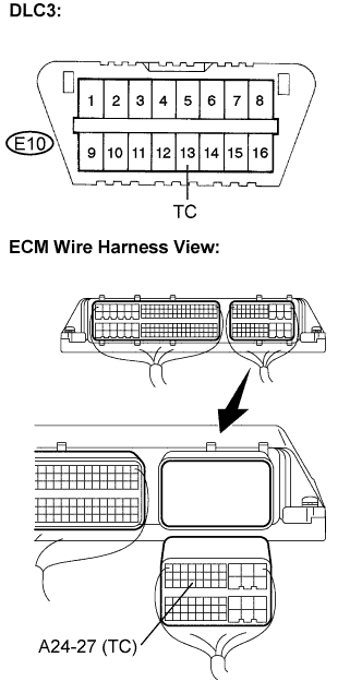
| 2.CHECK HARNESS AND CONNECTOR (ECM TO DLC3) |
Disconnect the ECM connector.
Measure the resistance according to the value(s) in the table below.
- Standard resistance:
Tester Connection
| Specified Condition
|
A24-27 (TC) - E10-13 (TC)
| Below 1 Ω
|
E10-13 (TC) - Body ground
| 10 kΩ or higher
|
Connect the connector.
| | REPAIR OR REPLACE HARNESS OR CONNECTOR (TC TERMINAL CIRCUIT) |
|
|
| 3.CHECK HARNESS AND CONNECTOR (DLC3 CG CIRCUIT) |
Measure the resistance according to the value(s) in the table below.
- Standard resistance:
Tester Connection
| Specified Condition
|
E10-4 (CG) - Body ground
| Below 1 Ω
|
| | REPAIR OR REPLACE HARNESS OR CONNECTOR (CG TERMINAL CIRCUIT) |
|
|
| 4.REPAIR OR REPLACE HARNESS OR CONNECTOR (TC TERMINAL CIRCUIT) |
Measure the resistance according to the value(s) in the table below.
- Standard resistance:
Tester Connection
| Specified Condition
|
E10-13 (TC) - Body ground
| 10 kΩ or higher
|
| | CHECK HARNESS AND CONNECTOR (TC TERMINAL CIRCUIT) |
|
|