Vehicle Stability Control System Tc And Cg Terminal Circuit
Brake. Camry. Acv40 Gsv40
DESCRIPTION
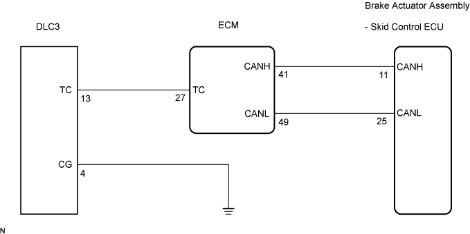
WIRING DIAGRAM
INSPECTION PROCEDURE
CHECK CAN COMMUNICATION SYSTEM
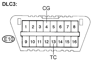
INSPECT DLC3
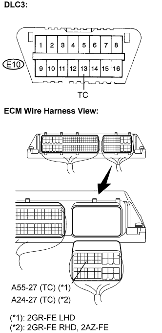
CHECK HARNESS AND CONNECTOR (TC of DLC3 - ECM)
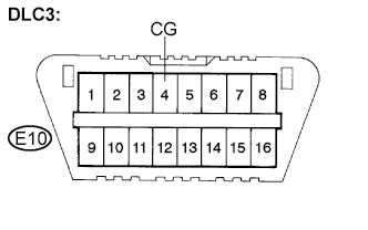
CHECK HARNESS AND CONNECTOR (CG of DLC3 - BODY GROUND)
CHECK ECM (TC of DLC3 INPUT)
VEHICLE STABILITY CONTROL SYSTEM - TC and CG Terminal Circuit |
DESCRIPTION
Connecting terminals TC and CG of the DLC3 causes the ECU to display the DTC by blinking the ABS warning light.
WIRING DIAGRAM
INSPECTION PROCEDURE
- NOTICE:
- When replacing the brake actuator assembly, perform zero point calibration (CAMRY_ACV40 RM000000XHR05BX.html).
| 1.CHECK CAN COMMUNICATION SYSTEM |
Check if the CAN communication system DTC is output (CAMRY_ACV40 RM000000WIB09JX.html for LHD, or CAMRY_ACV40 RM000000WIB09KX.html for RHD).
- Result:
Condition
| Proceed to
|
DTC is not output
| A
|
DTC is output
| B
|
| | INSPECT CAN COMMUNICATION SYSTEM |
|
|
Turn the ignition switch on (IG).
Measure the voltage according to the value(s) in the table below.
- Standard voltage:
Tester Connection
| Condition
| Specified Condition
|
E10-13 (TC) - E10-4 (CG)
| Ignition switch on (IG)
| 10 to 14 V
|
| 3.CHECK HARNESS AND CONNECTOR (TC of DLC3 - ECM) |
Turn the ignition switch off.
Disconnect the ECM connector.
Measure the resistance according to the value(s) in the table below.
- Standard resistance:
- 2GR-FE (LHD):
Tester Connection
| Condition
| Specified Condition
|
E10-13 (TC) - A55-27 (TC)
| Always
| Below 1 Ω
|
E10-13 (TC) - Body ground
| Always
| 10 kΩ or higher
|
- 2GR-FE (RHD):
Tester Connection
| Condition
| Specified Condition
|
E10-13 (TC) - A24-27 (TC)
| Always
| Below 1 Ω
|
E10-13 (TC) - Body ground
| Always
| 10 kΩ or higher
|
- 2AZ-FE:
Tester Connection
| Condition
| Specified Condition
|
E10-13 (TC) - A24-27 (TC)
| Always
| Below 1 Ω
|
E10-13 (TC) - Body ground
| Always
| 10 kΩ or higher
|
| | REPAIR OR REPLACE HARNESS OR CONNECTOR |
|
|
| 4.CHECK HARNESS AND CONNECTOR (CG of DLC3 - BODY GROUND) |
Measure the resistance according to the value(s) in the table below.
- Standard resistance:
Tester Connection
| Condition
| Specified Condition
|
E10-4 (CG) - Body ground
| Always
| Below 1 Ω
|
| | REPAIR OR REPLACE HARNESS OR CONNECTOR |
|
|
| 5.CHECK ECM (TC of DLC3 INPUT) |
Turn the ignition switch off.
Reconnect the ECM connector.
Using SST, connect terminals TC and CG of the DLC3.
Turn the ignition switch on (IG).
Check that the check engine warning light is blinking.
- Result:
Condition
| Proceed to
|
Check engine warning light is blinking
| A
|
Check engine warning light is not blinking
| B
|
- HINT:
- If troubleshooting has been carried out according to the Problem Symptoms Table, refer back to the table and proceed to the next step before replacing the part (CAMRY_ACV40 RM000000XHN08DX.html).
| | REPAIR OR REPLACE WIRE HARNESS OR ECM (TC of ECM CIRCUIT) |
|
|
| A |
|
|
|
| REPLACE BRAKE ACTUATOR ASSEMBLY |
|