Air Conditioning System Air Conditioning Compressor Magnetic Clutch Circuit
DESCRIPTION
WIRING DIAGRAM
INSPECTION PROCEDURE
CHECK CAN COMMUNICATION SYSTEM
READ VALUE USING INTELLIGENT TESTER
INSPECT FUSE (A/C NO. 2)
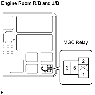
INSPECT RELAY (MGC)
CHECK HARNESS AND CONNECTOR (A/C AMPLIFIER - BATTERY)
INSPECT AIR CONDITIONING AMPLIFIER
INSPECT A/C COMPRESSOR
INSPECT MAGNETIC CLUTCH
CHECK HARNESS AND CONNECTOR (ENGINE ROOM R/B AND J/B - BATTERY)
AIR CONDITIONING SYSTEM - Air Conditioning Compressor Magnetic Clutch Circuit |
DESCRIPTION
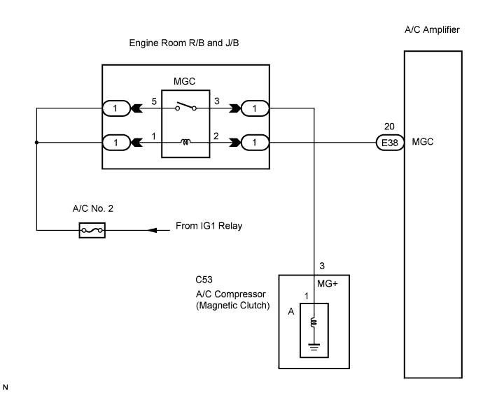
When the A/C amplifier is turned on, a magnetic clutch ON signal is sent from the MGC terminal of the A/C amplifier. Then, the MGC relay turns on to operate the magnetic clutch.
WIRING DIAGRAM
INSPECTION PROCEDURE
| 1.CHECK CAN COMMUNICATION SYSTEM |
Use the intelligent tester to check if the CAN Communication System is functioning normally.
- Result:
Result
| Proceed to
|
CAN DTC is not output
| A
|
CAN DTC is output
| B
|
| | GO TO CAN COMMUNICATION SYSTEM |
|
|
| 2.READ VALUE USING INTELLIGENT TESTER |
Connect the intelligent tester to the DLC3.
Turn the ignition switch to the ON position and turn the intelligent tester main switch on.
Turn the A/C switch on and off.
Select the item below in the Data List, and read the display on the intelligent tester.
Data List / Engine:Item
| Measure Item
| Normal Condition
| Diagnostic Note
|
A/C Signal
(A/C Signal)
| A/C signal / ON or OFF
| ON: A/C ON
OFF: A/C OFF
| -
|
- OK:
- The display is as specified in the normal condition column.
| | PROCEED TO NEXT CIRCUIT INSPECTION SHOWN IN PROBLEM SYMPTOMS TABLE |
|
|
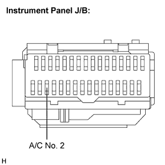
| 3.INSPECT FUSE (A/C NO. 2) |
Remove the A/C No. 2 fuse from the instrument panel J/B.
Measure the resistance of the fuse.
- Standard resistance:
Tester Item
| Condition
| Specified Condition
|
A/C No. 2 fuse
| Always
| Below 1 Ω
|
Reconnect the A/C No. 2 fuse to the instrument panel J/B.
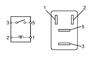
Remove the MGC relay from the engine room R/B and J/B.
Measure the resistance according to the value(s) in the table below.
- Standard resistance:
Tester Connection
| Specified Condition
|
3 - 5
| 10 kΩ or higher
|
3 - 5
| Below 1 Ω
(when battery voltage is applied to terminals 1 and 2)
|
Install the MGC relay to the engine room R/B and J/B.
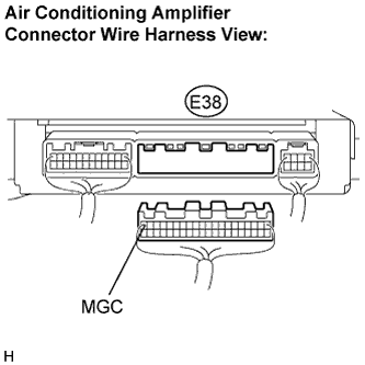
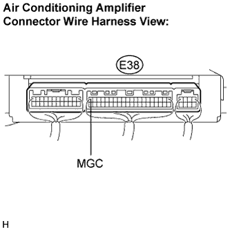
| 5.CHECK HARNESS AND CONNECTOR (A/C AMPLIFIER - BATTERY) |
Disconnect the connector from the A/C amplifier.
Measure the voltage according to the value(s) in the table below.
- Standard voltage:
Tester Connection
(Symbols)
| Condition
| Specified Condition
|
E38-20 (MGC) - Body ground
| Ignition switch: LOCK
| Below 1 V
|
E38-20 (MGC) - Body ground
| Ignition switch: ON
| 10 to 14 V
|
| | REPAIR OR REPLACE HARNESS OR CONNECTOR |
|
|
| 6.INSPECT AIR CONDITIONING AMPLIFIER |
Reconnect the connector to the A/C amplifier.
Measure the voltage according to the value(s) in the table below.
- Standard voltage:
Tester Connection
(Symbols)
| Condition
| Specified Condition
|
E38-20 (MGC) - Body ground
| Ignition switch: ON
A/C switch: OFF
| 10 to 14 V
|
E38-20 (MGC) - Body ground
| Ignition switch: ON
A/C switch: ON
| Below 1 V
|
| | REPLACE AIR CONDITIONING AMPLIFIER |
|
|
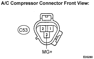
Disconnect the connector from the A/C compressor.
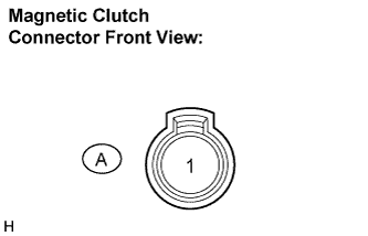
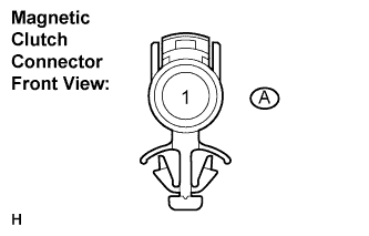
Disconnect the connector from the magnetic clutch.
Measure the resistance according to the value(s) in the table below.
- Standard resistance:
Tester Connection
(Symbols)
| Condition
| Specified Condition
|
C53-3 (MG+) - A-1
| Always
| Below 1 Ω
|
C53-3 (MG+) - Body ground
| Always
| 10 kΩ or higher
|
| 8.INSPECT MAGNETIC CLUTCH |
Measure the resistance according to the value(s) in the table below.
- Standard resistance:
Tester Connection
| Condition
| Specified Condition
|
A-1 - Body ground
| Always
| 3.4 to 3.8 Ω
|
When connector terminal A1 is connected to the positive (+) battery terminal, check that the following occurs: 1) the magnetic clutch's operating sound can be heard, and 2) the magnetic clutch's hub and rotor lock.
| 9.CHECK HARNESS AND CONNECTOR (ENGINE ROOM R/B AND J/B - BATTERY) |
Remove the MGC relay from the engine room R/B and J/B.
Turn the ignition switch to the ON position.
Measure the voltage according to the value(s) in the table below.
- Standard voltage:
Tester Connection
| Specified Condition
|
Relay block MGC relay terminal 5 - Body ground
| 10 to 14 V
|
Relay block MGC relay terminal 1 - Body ground
| 10 to 14 V
|
| | REPAIR OR REPLACE HARNESS OR CONNECTOR (ENGINE ROOM R/B AND J/B - A/C COMPRESSOR) |
|
|
| OK |
|
|
|
| REPAIR OR REPLACE HARNESS OR CONNECTOR |
|