CHECK ANY OTHER DTCS OUTPUT (IN ADDITION TO DTC P2A00)
PERFORM ACTIVE TEST USING INTELLIGENT TESTER (INJECTION VOLUME)
PERFORM CONFIRMATION DRIVING PATTERN
INSPECT AIR FUEL RATIO SENSOR (HEATER RESISTANCE)
INSPECT FUEL INJECTOR ASSEMBLY
PERFORM CONFIRMATION DRIVING PATTERN
PERFORM CONFIRMATION DRIVING PATTERN
DTC P2A00 A/F Sensor Circuit Slow Response (Bank 1 Sensor 1) |
DESCRIPTION
- HINT:
- Refer to DTC P2195 (Link).
| DTC No. | DTC Detection Condition | Trouble Area |
| P2A00 | Calculated value for air fuel ratio sensor response rate deterioration level is less than threshold (2 trip detection logic) |
|
CONFIRMATION DRIVING PATTERN
- HINT:
- Performing this confirmation driving pattern will activate the A/F sensor response monitor.

- Connect the intelligent tester to the DLC3.
- Turn the ignition switch to ON.
- Turn the tester on.
- Clear DTCs (even if no DTCs are stored, perform the clear DTC operation).
- Turn the ignition switch off and wait for at least 30 seconds.
- Turn the ignition switch to ON and turn the tester on.
- Start the engine and warm it up until the engine coolant temperature is 75°C (167°F) or higher [A].
- Drive the vehicle at approximately 60 km/h (38 mph) for 10 minutes or more in a city area [B].
- CAUTION:
- When performing the confirmation driving pattern, obey all speed limits and traffic laws.
- Enter the following menus: Powertrain / Engine and ECT / DTC [C].
- Read the pending DTCs.
- HINT:
- If a pending DTC is output, the system is malfunctioning.
- If a pending DTC is not output, perform the following procedure.
- Enter the following menus: Powertrain / Engine and ECT / Utility / All Readiness.
- Input the DTC: P2A00.
- Check the DTC judgment result.
Tester Display Description NORMAL - DTC judgment completed
- System normal
ABNORMAL - DTC judgment completed
- System abnormal
INCOMPLETE - DTC judgment not completed
- Perform driving pattern after confirming DTC enabling conditions
UNKNOWN - Unable to perform DTC judgment
- Number of DTCs which do not fulfill DTC preconditions has reached ECU memory limit
- HINT:
- If the judgment result shows NORMAL, the system is normal.
- If the judgment result shows ABNORMAL, the system has a malfunction.
- If the test result is INCOMPLETE or UNKNOWN and no pending DTC is output, perform the following procedure.
- DTC judgment completed
- Drive the vehicle at a speed between 75 and 100 km/h (47 and 63 mph) for 10 minutes [D].
- CAUTION:
- When performing the confirmation driving pattern, obey all speed limits and traffic laws.
- Check the DTC judgment result [E].
WIRING DIAGRAM
Refer to DTC P2195 (CAMRY_ACV40 RM000000WC40GFX_07.html).INSPECTION PROCEDURE
- HINT:
- Malfunctioning areas can be identified by performing the Control the Injection Volume for A/F Sensor function provided in the Active Test. The Control the Injection Volume for A/F Sensor function can help to determine whether the air fuel ratio sensor, heated oxygen sensor and other potential trouble areas are malfunctioning.
- The following instructions describe how to conduct the Control the Injection Volume for A/F Sensor operation using the intelligent tester.
- Connect the intelligent tester to the DLC3.
- Start the engine.
- Turn the tester on.
- Warm up the engine at an engine speed of 2500 rpm for approximately 90 seconds.
- Enter the following menus: Powertrain / Engine and ECT / Active Test / Control the Injection Volume for A/F Sensor.
- Perform the Active Test operation with the engine in an idling condition (press the RIGHT or LEFT button to change the fuel injection volume).
- Monitor the output voltages of the air fuel ratio and heated oxygen sensors (AFS Voltage B1S1 and O2S B1S2) displayed on the tester.
- HINT:
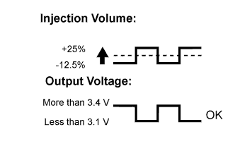
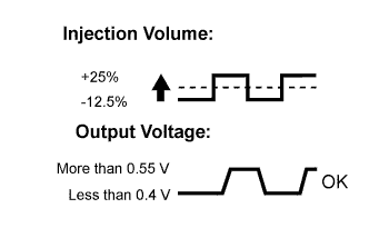
- The Control the Injection Volume for A/F Sensor operation lowers the fuel injection volume by 12.5% or increases the injection volume by 25%.
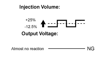
- Each sensor reacts in accordance with increases and decreases in the fuel injection volume.
| Tester Display (Sensor) | Injection Volume | Status | Voltage |
| AFS Voltage B1S1 (Air fuel ratio) | +25% | Rich | Less than 3.1 V |
| -12.5% | Lean | More than 3.4 V | |
| O2S B1S2 (Heated oxygen) | +25% | Rich | More than 0.55 V |
| -12.5% | Lean | Less than 0.4 V |
- NOTICE:
- The air fuel ratio sensor has an output delay of a few seconds and the heated oxygen sensor has a maximum output delay of approximately 20 seconds.
| Case | Air Fuel Ratio Sensor (Sensor 1) Output Voltage | Heated Oxygen Sensor (Sensor 2) Output Voltage | Main Suspected Trouble Area |
| 1 |  |  | - |
| 2 |  |  |
|
| 3 |  |  |
|
| 4 |  |  |
|
- Following the Control the Injection Volume for A/F Sensor procedure enables technicians to check and graph the voltage outputs of both the air fuel ratio and heated oxygen sensors.
- To display the graph, enter the following menus: Powertrain / Engine and ECT / Active Test / Control the Injection Volume for A/F Sensor / AFS Voltage B1S1 and O2S B1S2; then press the graph button on the Data List screen.
- NOTICE:
- Inspect the fuses for circuits related to this system before performing the following inspection procedure.
- HINT:
- DTC P2A00 may be also set, when the air fuel ratio is stuck rich or lean.
- A low air fuel ratio sensor voltage could be caused by a rich air fuel mixture. Check for conditions that would cause the engine to run rich.
- A high air fuel ratio sensor voltage could be caused by a lean air fuel mixture. Check for conditions that would cause the engine to run lean.
- Read freeze frame data using the intelligent tester. The ECM records vehicle and driving condition information as freeze frame data the moment a DTC is stored. When troubleshooting, freeze frame data can be helpful in determining whether the vehicle was running or stopped, whether the engine was warmed up or not, whether the air fuel ratio was lean or rich, as well as other data recorded at the time of a malfunction.
- Sensor 1 refers to the sensor closest to the engine assembly.
- Sensor 2 refers to the sensor farthest away from the engine assembly.
| 1.CHECK ANY OTHER DTCS OUTPUT (IN ADDITION TO DTC P2A00) |
Connect the intelligent tester to the DLC3.
Turn the ignition switch to ON.
Turn the tester on.
Enter the following menus: Powertrain / Engine and ECT / DTC.
Read the DTCs.
- Result:
Result Proceed to DTC P2A00 is output A DTC P2A00 and other DTCs are output B
- HINT:
- If any DTCs other than P2A00 are output, troubleshoot those DTCs first.
|
| ||||
| A | |
| 2.PERFORM ACTIVE TEST USING INTELLIGENT TESTER (INJECTION VOLUME) |
Connect the intelligent tester to the DLC3.
Start the engine.
Turn the tester on.
Warm up the engine and run the engine at an engine speed of 2500 rpm for approximately 90 seconds.
Enter the following menus: Powertrain / Engine and ECT / Active Test / Control the Injection Volume / All Data / AFS Voltage B1S1 and O2S B1S2.
Perform the Control the Injection Volume operation with the engine idling.
Monitor the output voltages of the air fuel ratio and heated oxygen sensors (AFS Voltage B1S1 and O2S B1S2) displayed on the tester.
- HINT:
- Change the fuel injection volume within the range of - 12.0% to +12.0%. The injection volume can be changed in fine gradations.
- The air fuel ratio sensor has an output delay of a few seconds and the heated oxygen sensor has a maximum output delay of approximately 20 seconds.
Tester Display (Sensor) Injection Volume Status Voltage AFS Voltage B1S1
(Air fuel ratio)+12% Rich Less than 3.1 V AFS Voltage B1S1
(Air fuel ratio)-12% Lean More than 3.4 V O2S B1S2
(Heated oxygen)+12% Rich More than 0.55 V O2S B1S2
(Heated oxygen)-12% Lean Less than 0.4 V - Result:
Status of AFS Voltage B1S1 Status of O2S B1S2 Air Fuel Ratio Condition and Air Fuel Ratio Sensor Condition Misfire Suspected Trouble Area Proceed to Lean/Rich Lean/Rich Normal - - A Lean Lean Actual air fuel ratio lean May occur - PCV valve and hose
- PCV hose connections
- Fuel injector assembly blockage
- Gas leaks from exhaust system
- Intake system
- Fuel pressure
- Mass air flow meter sub-assembly
- Engine coolant temperature sensor
B Rich Rich Actual air fuel ratio rich - - Fuel injector assembly leakage or blockage
- Gas leaks from exhaust system
- Ignition system
- Fuel pressure
- Mass air flow meter sub-assembly
- Engine coolant temperature sensor
B Lean Lean/Rich Air fuel ratio sensor malfunction - Air fuel ratio sensor C Rich Lean/Rich Air fuel ratio sensor malfunction - Air fuel ratio sensor C - PCV valve and hose
Rich: During the Control the Injection Volume Active Test, the AFS Voltage is consistently below 3.1 V, and the O2S is consistently higher than 0.55 V.
Lean/Rich: During the Control the Injection Volume Active Test, the output voltage of the heated oxygen sensor alternates correctly.
Refer to "Data List / Active Test" [AFS Voltage B1S1 and O2S B1S2] (CAMRY_ACV40 RM000000PDN0GRX.html).
|
| ||||
|
| ||||
| A | |
| 3.PERFORM CONFIRMATION DRIVING PATTERN |
Connect the intelligent tester to the DLC3.
Turn the ignition switch to ON.
Turn the tester on.
Clear the DTCs (CAMRY_ACV40 RM000000PDK0LEX.html).
Turn the ignition switch off and wait for 30 seconds.
Turn the ignition switch to ON and turn the tester on.
Start the engine and warm it up.
Drive the vehicle in accordance with the driving pattern described in Confirmation Driving Pattern.
Enter the following menus: Powertrain / Engine and ECT / Utility / All Readiness.
Input the DTC: P2A00.
Check the DTC judgment result.
Result Result Proceed to NORMAL (DTC is not output) A ABNORMAL (DTC P2A00 is output) B
|
| ||||
|
| ||||
| 4.INSPECT AIR FUEL RATIO SENSOR (HEATER RESISTANCE) |
Disconnect the air fuel ratio sensor connector.
 |
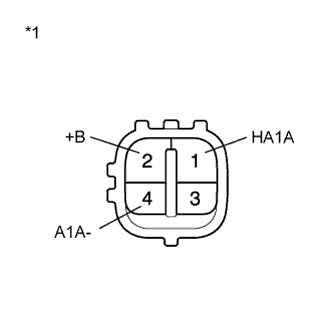
Measure the resistance according to the value(s) in the table below.
- Standard Resistance:
Tester Connection Condition Specified Condition 1 (HA1A) - 2 (+B) 20°C (68°F) 1.8 to 3.4 Ω 1 (HA1A) - 4 (A1A-) Always 10 kΩ or higher
Text in Illustration *1 Component without harness connected
(Air Fuel Ratio Sensor)
Reconnect the air fuel ratio sensor connector.
|
| ||||
| OK | |
| 5.CHECK INTAKE SYSTEM |
Check the intake system for vacuum leaks.
- OK:
- No leaks in the intake system
|
| ||||
| OK | |
| 6.CHECK FUEL PRESSURE |
Check the fuel pressure (CAMRY_ACV40 RM000000YCR00RX_01_0002.html).
|
| ||||
| OK | |
| 7.INSPECT FUEL INJECTOR ASSEMBLY |
Inspect the fuel injector assembly (CAMRY_ACV40 RM000000YCT00PX.html).
|
| ||||
| OK | |
| 8.REPLACE AIR FUEL RATIO SENSOR |
Replace the air fuel ratio sensor (CAMRY_ACV40 RM0000012OI006X.html).
| NEXT | |
| 9.PERFORM CONFIRMATION DRIVING PATTERN |
Connect the intelligent tester to the DLC3.
Turn the ignition switch to ON.
Turn the tester on.
Clear the DTCs (CAMRY_ACV40 RM000000PDK0LEX.html).
Turn the ignition switch off and wait for 30 seconds.
Turn the ignition switch to ON and turn the tester on.
Start the engine and warm it up.
Drive the vehicle in accordance with the driving pattern described in Confirmation Driving Pattern.
Enter the following menus: Powertrain / Engine and ECT / Utility / All Readiness.
Input the DTC: P2A00.
Check the DTC judgment result.
Result Result Proceed to ABNORMAL (DTC P2A00 is output) A NORMAL (DTC is not output) B
|
| ||||
| A | |
| 10.REPLACE ECM |
Replace the ECM (CAMRY_ACV40 RM0000017UO02YX.html).
| NEXT | |
| 11.PERFORM CONFIRMATION DRIVING PATTERN |
Connect the intelligent tester to the DLC3.
Turn the ignition switch to ON.
Turn the tester on.
Clear the DTCs (CAMRY_ACV40 RM000000PDK0LEX.html).
Turn the ignition switch off and wait for 30 seconds.
Turn the ignition switch to ON and turn the tester on.
Start the engine and warm it up.
Drive the vehicle in accordance with the driving pattern described in Confirmation Driving Pattern.
Enter the following menus: Powertrain / Engine and ECT / Utility / All Readiness.
Input the DTC: P2A00.
Check that the DTC judgment result is NORMAL.
| NEXT | ||
| ||
| 12.INSPECT FUEL PUMP |
Inspect the fuel pump (CAMRY_ACV40 RM0000017RH009X.html).
|
| ||||
| OK | ||
| ||