CHECK HARNESS AND CONNECTOR (BATTERY - PARK/NEUTRAL POSITION)
CHECK HARNESS AND CONNECTOR (OUTPUT SIGNAL)
INSPECT PARK/NEUTRAL POSITION SWITCH ASSEMBLY
CHECK HARNESS AND CONNECTOR (PARK/NEUTRAL POSITION SWITCH - ECM)
CHECK HARNESS AND CONNECTOR (PARK/NEUTRAL POSITION SWITCH - TRANSMISSION CONTROL SWITCH)
INSPECT TRANSMISSION CONTROL SWITCH
CHECK HARNESS AND CONNECTOR (TRANSMISSION CONTROL SWITCH - ECM)
CHECK HARNESS AND CONNECTOR (PARK/NEUTRAL POSITION SWITCH - ECM)
DTC P0705 Transmission Range Sensor Circuit Malfunction (PRNDL Input) |
DESCRIPTION
The park/neutral position switch detects the shift lever position and sends signals to the ECM.| DTC No. | DTC Detection Condition | Trouble Area |
| P0705 | (A) Any 2 or more signals of the following are ON simultaneously (2-trip detection logic)
(D) Both 1 and 2 are met (2-trip detection logic)
|
|
MONITOR DESCRIPTION
These DTCs indicate a problem with the park/neutral position switch and the wire harness in the park/neutral position switch circuit.The park/neutral position switch detects the shift lever position and sends a signal to the ECM.
For security, the park/neutral position switch detects the shift lever position so that engine can be started only when the shift lever is in the P or N position
The park/neutral position switch sends a signal to the ECM according to the shift position (P, R, N or D). The ECM determines that there is a problem with the switch or related parts if in receives more than 1 position signal simultaneously. The ECM will turn on the MIL and store the DTC.
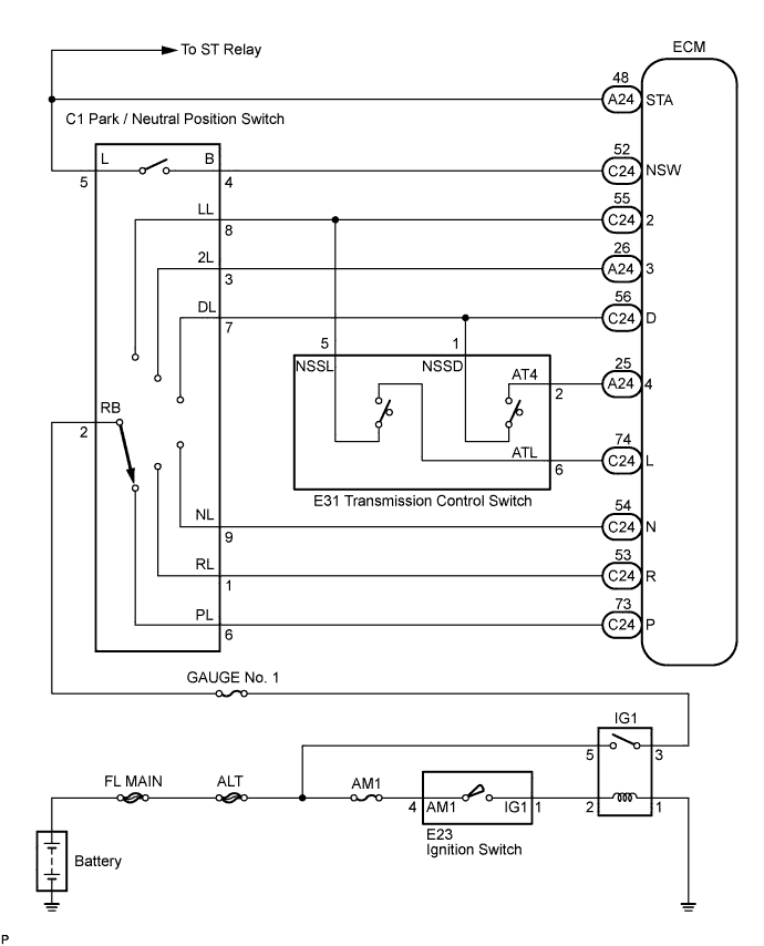
WIRING DIAGRAM
INSPECTION PROCEDURE
| DATA LIST |
- HINT:
- Using the intelligent tester Data List allows switch, sensor, actuator and other item values to be read without removing any parts. Reading the Data List early in troubleshooting is one way to shorten labor time.
- NOTICE:
- In the table below, the values listed under "Normal Condition" are reference values. Do not depend solely on these reference values when deciding whether a part is faulty or not.
Warm up the engine.
Turn the ignition switch off.
Connect the intelligent tester to the DLC3.
Turn the ignition switch to the ON position.
Turn on the tester.
Select the item "Enter / Powertrain / ECT / Data List".
Follow the instructions on the tester and read the Data List.
Item Measurement Item / Range (Display) Normal Condition Diagnostic Note Neutral Position SW Signal PNP SW Status / ON or OFF Shift lever position is;
P and N: ON
Except P or N: OFFWhen the shift lever position displayed on the intelligent tester differs from the actual position, adjustment of the PNP switch or the shift cable may be incorrect. Shift SW Status (R Range) PNP SW Status / ON or OFF Shift lever position is;
R: ON
Except R: OFFWhen the shift lever position displayed on the intelligent tester differs from the actual position, adjustment of the PNP switch or the shift cable may be incorrect. Shift SW Status (D Range) PNP SW Status / ON or OFF Shift lever position is;
D and 4: ON
Except D and 4: OFFWhen the shift lever position displayed on the intelligent tester differs from the actual position, adjustment of the PNP switch or the shift cable may be incorrect. Shift SW Status (2 Range) PNP SW Status / ON or OFF Shift lever position is;
2 and L: ON
Except 2 and L: OFFWhen the shift lever position displayed on the intelligent tester differs from the actual position, adjustment of the PNP switch or the shift cable may be incorrect. Shift SW Status (L Range) PNP SW Status / ON or OFF Shift lever position is;
L: ON
Except L: OFFWhen the shift lever position displayed on the intelligent tester differs from the actual position, adjustment of the PNP switch or the shift cable may be incorrect. Shift SW Status (4 or D Range) PNP SW Status / ON or OFF Shift lever position is;
4: ON
Except 4: OFFWhen the shift lever position displayed on the intelligent tester differs from the actual position, adjustment of the PNP switch or the shift cable may be incorrect. Shift SW Status (3 Range) PNP SW Status / ON or OFF Shift lever position is;
3: ON
Except 3: OFFWhen the shift lever position displayed on the intelligent tester differs from the actual position, adjustment of the PNP switch or the shift cable may be incorrect.
| 1.CHECK HARNESS AND CONNECTOR (BATTERY - PARK/NEUTRAL POSITION) |
Disconnect the park/neutral position switch connector.
 |
Turn the ignition switch on (IG).
Measure voltage according to the value(s) in the table below.
- Standard voltage:
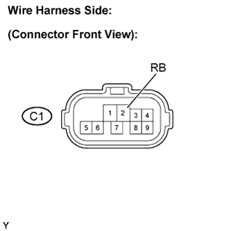
Tester Connection Specified Condition 2 - Body ground 10 to 14 V
|
| ||||
| OK | |
| 2.CHECK HARNESS AND CONNECTOR (OUTPUT SIGNAL) |
Turn the ignition switch on (IG).
 |
Measure voltage according to the value(s) in the table below.
- Standard voltage:
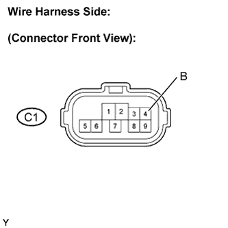
Tester Connection Specified Condition 4 - Body ground 10 to 14 V
|
| ||||
| OK | |
| 3.INSPECT PARK/NEUTRAL POSITION SWITCH ASSEMBLY |
Measure resistance according to the value(s) in the table below when the shift lever is moved to each position.
- Standard resistance:
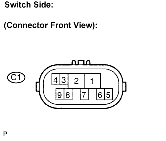
Shift Position Tester Connection Specified Condition P 2 - 6 and 4 - 5 Below 1 Ω Except P 10 kΩ or higher R 2 - 1 Below 1 Ω Except R 10 kΩ or higher N 2 - 9 and 4 - 5 Below 1 Ω Except N 10 kΩ or higher D and 4 2 - 7 Below 1 Ω Except D and 4 10 kΩ or higher 3 2 - 3 Below 1 Ω Except 3 10 kΩ or higher 2 and L 2 - 8 Below 1 Ω Except 2 and L 10 kΩ or higher
 |
|
| ||||
| OK | |
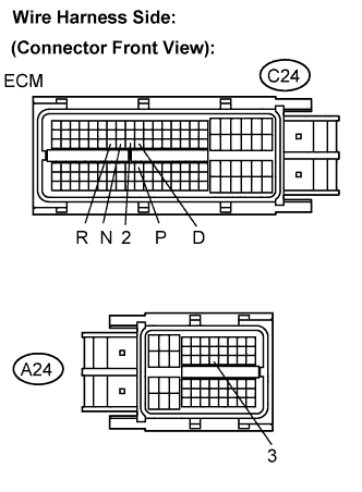
| 4.CHECK HARNESS AND CONNECTOR (PARK/NEUTRAL POSITION SWITCH - ECM) |
Connect the park/neutral position switch connector.
 |
Disconnect the ECM connectors.
Turn the ignition switch on (IG), and measure the voltage according to the value(s) in the table below when the shift lever is moved to each position.
- Standard voltage:
Shift Position Tester Connection Specified Condition P C24-73 (P) - Body ground 10 to 14 V Except P Below 1 V N C24-54 (N) - Body ground 10 to 14 V Except N Below 1 V R C24-53 (R) - Body ground 10 to 14 V* Except R Below 1 V D and 4 C24-56 (D) - Body ground 10 to 14 V Except D and 4 Below 1 V 3 A24-26 (3) - Body ground 10 to 14 V Except 3 Below 1 V 2 and L C24-55 (2) - Body ground 10 to 14 V Except 2 and L Below 1 V
- HINT:
- *: The voltage will drop slightly due to lighting up of the back up light.
|
| ||||
| OK | |
| 5.CHECK HARNESS AND CONNECTOR (PARK/NEUTRAL POSITION SWITCH - TRANSMISSION CONTROL SWITCH) |
Disconnect the transmission control switch connector of shift lock control unit assembly.
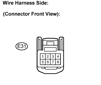 |
Measure the voltage according to the value(s) in the table below when the shift lever is moved to each position.
- Standard voltage:
Shift Position Tester Connection Specified Condition D and 4 1 - Body ground 10 to 14 V Except D and 4 Below 1 V 2 and L 5 - Body ground 10 to 14 V Except 2 and L Below 1 V
|
| ||||
| OK | |
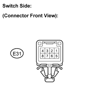
| 6.INSPECT TRANSMISSION CONTROL SWITCH |
Measure the resistance according to the value(s) in the table below when the shift lever is moved to each position.
- Standard resistance:
Shift Position Tester Connection Specified Condition 4 and 3 1 - 2 Below 1 Ω Except 4 and 3 10 kΩ or higher L 5 - 6 Below 1 Ω Except L 10 kΩ or higher
 |
|
| ||||
| OK | |
| 7.CHECK HARNESS AND CONNECTOR (TRANSMISSION CONTROL SWITCH - ECM) |
Connect the transmission control switch connector of shift lock control unit assembly.
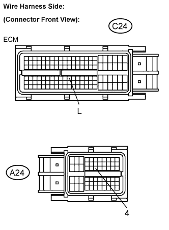 |
Turn the ignition switch to the ON position, and measure the voltage according to the value(s) in the table below when the shift lever is moved to each position.
- Standard voltage:
Shift Position Tester Connection Specified Condition 4 A24-25 (4) - Body ground 10 to 14 V Except 4 Below 1 V L C24-74 (L) - Body ground 10 to 14 V Except L Below 1 V
|
| ||||
| OK | ||
| ||
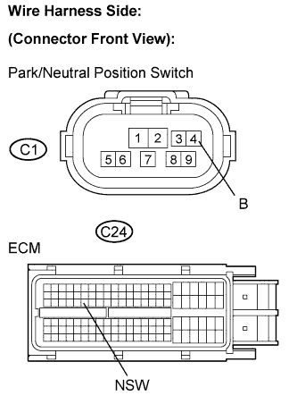
| 8.CHECK HARNESS AND CONNECTOR (PARK/NEUTRAL POSITION SWITCH - ECM) |
Disconnect the ECM connectors.
 |
Turn the ignition switch off.
Measure resistance according to the value(s) in the table below.
- Standard resistance (Check for open):
Tester Connection Specified Condition B (C1-4) - NSW (C24-52) Below 1 Ω
- Standard resistance (Check for short):
Tester Connection Specified Condition B (C1-4) or NSW (C24-52) - Body ground 10 kΩ or higher
|
| ||||
| OK | ||
| ||