Body Electrical. Camry. Acv40 Gsv40
Door Lock. Camry. Acv40 Gsv40
Power Door Lock Control System -- Terminals Of Ecu |
| CHECK MAIN BODY ECU (INSTRUMENT PANEL JUNCTION BLOCK) |
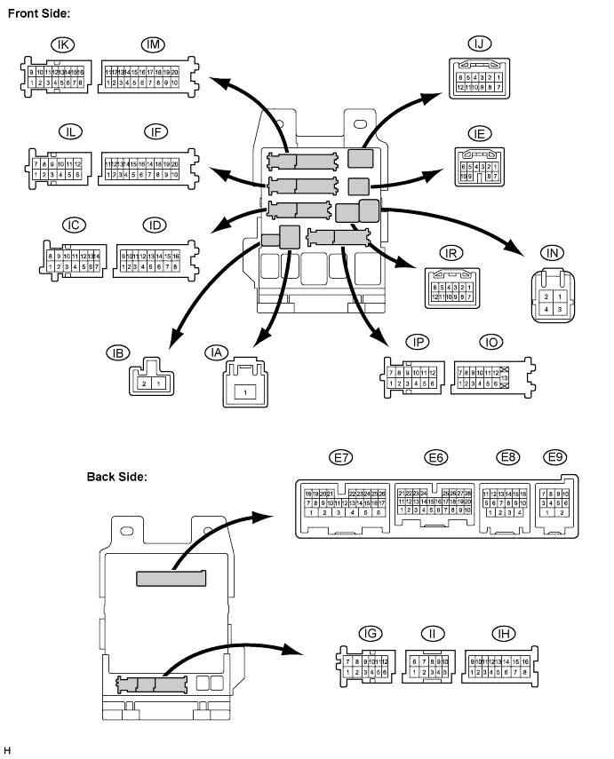
Disconnect the E6, E7, IO, IK, IM, ID, IA, IF, IJ, and E9 J/B and ECU connectors.
Measure the voltage and resistance according to the value(s) in the table below.
*1: LHDSymbols (Terminal No.) Wiring Color Terminal Description Condition Specified Condition DCTY (E7-24) - Body ground L (*1), Y (*2) - Body ground Driver door courtesy switch Driver door CLOSED → OPEN 10 kΩ or higher → Below 1 Ω RCTY (E6-5) - Body ground GR - Body ground Rear right door courtesy switch input Rear right door CLOSED → OPEN 10 kΩ or higher → Below 1 Ω PCTY (E6-21) - Body ground Y (*1), L (*2) - Body ground Passenger door courtesy switch input Passenger door CLOSED → OPEN 10 kΩ or higher → Below 1 Ω LCTY (IO-7) - Body ground LG - Body ground Rear left door courtesy switch input Rear left door CLOSED → OPEN 10 kΩ or higher → Below 1 Ω GND2 (IM-9) - Body ground W-B - Body ground Ground Always Below 1 Ω IG (IA-1) - Body ground B - Body ground Engine power supply Ignition switch on (IG) → off 10 to 14 V → Below 1 V GND1 (IF-10) - Body ground W-B - Body ground Ground Always Below 1 Ω ACC (IA-1) - Body ground B - Body ground ACC power supply Always 10 to 14 V L1 (IJ-3) - Body ground L(*2) - Body ground Driver door control switch LOCK input Driver door control switch OFF → LOCK 10 kΩ or higher → Below 1 Ω UL1 (IJ-4) - Body ground G(*2) - Body ground Driver door control switch UNLOCK input Driver door control switch OFF → UNLOCK 10 kΩ or higher → Below 1 Ω L1 (IK-15) - Body ground V(*1) - Body ground Driver door control switch LOCK input Driver door control switch OFF → LOCK 10 kΩ or higher →
Below 1 ΩUL1 (IK-12) - Body ground G(*1) - Body ground Driver door control switch UNLOCK input Driver door control switch OFF → UNLOCK 10 kΩ or higher → Below 1 Ω KSW (E9-5) - Body ground L - Body ground Unlock warning switch signal input No key is in ignition key cylinder → Key is in ignition key cylinder 10 kΩ or higher → Below 1 Ω LGCY (E6-25) - Body ground W - Body ground Luggage compartment door courtesy switch input Luggage compartment door CLOSED → OPEN 10 kΩ or higher → Below 1 Ω TKUL (E6-2) - Body ground R - Body ground Luggage compartment door key-linked door unlock input Using mechanical key, operate luggage compartment door lock cylinder to LOCK → OPEN → UNLOCK 10 kΩ or higher → Below 1 Ω → 10 kΩ or higher BECU (ID-10) - Body ground O - Body ground +B (BECU) power supply Always 10 to 14 V
*2: RHD
If the result is not as specified, there may be a malfunction on the wire harness side.Reconnect the J/B and ECU connectors.
Measure the voltage according to the value(s) in the table below.
If the result is not as specified, the main body ECU (instrument panel J/B) may have a malfunction.Symbols (Terminal No.) Wiring Color Terminal Description Condition Specified Condition LSWP (E6-27) - Body ground GR (*1), L (*2) - Body ground Rear left door lock position switch input Rear left door UNLOCK → LOCK Below 1 V →
10 to 14 V (or pulse generation)LSWP (E6-27) - Body ground GR (*1), L (*2) - Body ground Rear right door lock position switch input Rear right door UNLOCK → LOCK Below 1 V →
10 to 14 V (or pulse generation)LSWD (E7-9) - Body ground L (*1), Y (*2) - Body ground Driver door lock position switch input Driver door UNLOCK → LOCK Below 1 V →
10 to 14 V (or pulse generation)UL2 (IK-7) - Body ground GR - Body ground Driver door key-linked door unlock input Using mechanical key, operate driver door lock cylinder to LOCK → UNLOCK Below 1 V →
10 to 14 V (or pulse generation)L2 (IK-16) - Body ground BR - Body ground Driver door key-linked door lock input Using mechanical key, operate driver door lock cylinder to UNLOCK → LOCK Below 1 V →
10 to 14 V (or pulse generation)UL2 (IK-7) - Body ground GR - Body ground Front passenger door key-linked door unlock input Using mechanical key, operate passenger door lock cylinder to LOCK → UNLOCK Below 1 V →
10 to 14 V (or pulse generation)L2 (IJ-5) - Body ground W - Body ground Front passenger door key-linked door lock input Using mechanical key, operate passenger door lock cylinder to UNLOCK → LOCK Below 1 V →
10 to 14 V (or pulse generation)ACT+ (IJ-1) - Body ground L - Body ground Door lock motor LOCK drive output (Front passenger door) Door control switch (Master switch or passenger side switch) or driver side door key cylinder OFF → LOCK → OFF Below 1 V →
10 to 14 V →
Below 1 VACT+ (IP-11) - Body ground W - Body ground Door lock motor LOCK drive output (Rear door LH) Door control switch (Master switch or passenger side switch) or driver side door key cylinder OFF → LOCK → OFF Below 1 V →
10 to 14 V →
Below 1 VACT+ (IF-5) - Body ground L - Body ground Door lock motor LOCK drive output (Rear door RH) Door control switch (Master switch or passenger side switch) or driver side door key cylinder OFF → LOCK → OFF Below 1 V →
10 to 14 V →
Below 1 VACT- (IP-6) - Body ground G - Body ground Door lock motor UNLOCK drive output (Rear door LH) Door control switch (Master switch or passenger side switch) or driver side door key cylinder OFF → UNLOCK → OFF Below 1 V →
10 to 14 V →
Below 1 VACT- (IF-18) - Body ground B - Body ground Door lock motor UNLOCK drive output (Rear door RH) Door control switch (Master switch or passenger side switch) or driver side door key cylinder OFF → UNLOCK → OFF Below 1 V →
10 to 14 V →
Below 1 VTR+ (E7-1) - Body ground B - Body ground Door lock motor UNLOCK drive output (Luggage compartment door) Luggage compartment open switch (Transmitter) or luggage compartment door key cylinder OFF → UNLOCK → OFF Below 1 V →
10 to 14 V →
Below 1 VACT- (IJ-2) - Body ground LG - Body ground Door lock motor UNLOCK drive output (Driver door) Door control switch (Master switch or passenger side switch) or driver side door key cylinder OFF → UNLOCK → OFF Below 1 V →
10 to 14 V →
Below 1 VACT+ (IK-2) - Body ground W - Body ground Door lock motor LOCK drive output (Driver door) Door control switch (Master switch or passenger side switch) or driver side door key cylinder OFF → LOCK → OFF Below 1 V →
10 to 14 V →
Below 1 VACT- (IJ-2) - Body ground LG - Body ground Door lock motor UNLOCK drive output (Front passenger) Door control switch (Master switch or passenger side switch) or driver side door key cylinder OFF → UNLOCK → OFF Below 1 V →
10 to 14 V →
Below 1 VLSWP (E6-27) - Body ground GR (*1), L (*2) - Body ground Rear right door lock position switch input Rear right door UNLOCK → LOCK Below 1 V →
10 to 14 V (or pulse generation)LSWP (E6-27) - Body ground GR (*1), L (*2) - Body ground Passenger door lock position switch input Passenger door UNLOCK → LOCK Below 1 V →
10 to 14 V (or pulse generation)