DESCRIPTION
WIRING DIAGRAM
INSPECTION PROCEDURE
READ VALUE USING INTELLIGENT TESTER (STARTER SIGNAL)
INSPECT PARK/NEUTRAL POSITION SWITCH ASSEMBLY
REPLACE PARK/NEUTRAL POSITION SWITCH ASSEMBLY
READ VALUE USING INTELLIGENT TESTER (STARTER SIGNAL)
INSPECT CLUTCH START SWITCH ASSEMBLY
REPLACE CLUTCH START SWITCH ASSEMBLY
READ VALUE USING INTELLIGENT TESTER (STARTER SIGNAL)
INSPECT IGNITION SWITCH ASSEMBLY
REPLACE IGNITION SWITCH ASSEMBLY
READ VALUE USING INTELLIGENT TESTER (STARTER SIGNAL)
REPAIR OR REPLACE HARNESS OR CONNECTOR (PNP SWITCH OR CLUTCH START SWITCH - STA TERMINAL OF ECM)
CHECK WHETHER DTC OUTPUT RECURS
DTC P0617 Starter Relay Circuit High |
DESCRIPTION
While the engine is being cranked, the positive battery voltage is applied to terminal STA of the ECM. If the ECM detects the Starter Control (STA) signal while the vehicle is being driven, it determines that there is a malfunction in the STA circuit. The ECM then illuminates the MIL and sets the DTC.This monitor runs when the vehicle is driven at 20 km/h (12.4 mph) for over 20 seconds.DTC No.
| DTC Detection Condition
| Trouble Area
|
P0617
| When conditions (a), (b) and (c) are met, positive (+B) battery voltage 10.5 V or more applied to ECM for 20 seconds (1 trip detection logic)
- (a) Vehicle speed 20 km/h (12.4 mph) or more
- (b) Engine speed 1,000 rpm or more
- (c) STA signal ON
| - Park/Neutral Position (PNP) switch (Automatic transaxle)
- Clutch start switch (Manual transaxle)
- Starter relay circuit
- Ignition switch
- ECM
|
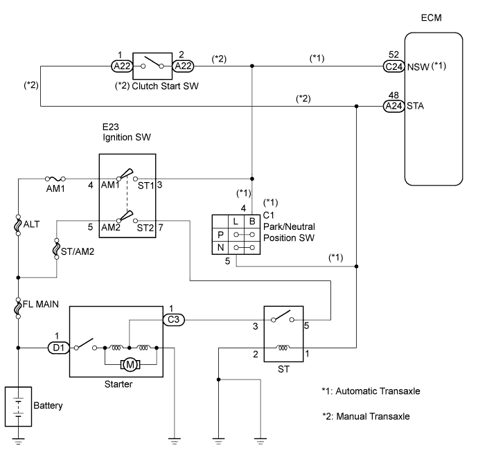
WIRING DIAGRAM
INSPECTION PROCEDURE
- HINT:
- The following troubleshooting flowchart is based on the premise that the engine is cranked normally.
If the engine does not crank, proceed to the problem symptoms table (CAMRY_ACV40 RM000000PDG018X.html).
- Read freeze frame data using the intelligent tester. The ECM records vehicle and driving condition information as freeze frame data the moment a DTC is stored. When troubleshooting, freeze frame data can help determine if the vehicle was moving or stationary, if the engine was warmed up or not, if the air-fuel ratio was lean or rich, and other data from the time the malfunction occurred.
| 1.READ VALUE USING INTELLIGENT TESTER (STARTER SIGNAL) |
Connect the intelligent tester to the DLC3.
Turn the ignition switch to the ON position and turn the tester on.
Select the following menu items: Powertrain / Engine and ECT / Data List / Starter Signal.
Read the value displayed on the tester when the ignition switch is in the ON and START positions.
- OK:
Ignition Switch Position
| STARTER SIG
|
ON
| OFF
|
START
| ON
|
| OK |
|
|
|
| CHECK FOR INTERMITTENT PROBLEMS |
|
| 2.INSPECT PARK/NEUTRAL POSITION SWITCH ASSEMBLY |
- HINT:
- For vehicles with the manual transaxle, proceed to step 5.
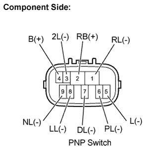
Disconnect the C1 PNP switch connector.
Measure the resistance when the transaxle gear selector lever is moved to each position.
- Standard resistance:
Gear Selector
Lever Position
| Tester Connection
| Specified Condition
|
P
| 2 - 6, 4 - 5
| Below 1 Ω
|
R
| 1 - 2
| Below 1 Ω
|
N
| 2 - 9, 4 - 5
| Below 1 Ω
|
D
| 2 - 7
| Below 1 Ω
|
2
| 2 - 3
| Below 1 Ω
|
L
| 2 - 8
| Below 1 Ω
|
Reconnect the PNP switch connector.
| 3.REPLACE PARK/NEUTRAL POSITION SWITCH ASSEMBLY |
| 4.READ VALUE USING INTELLIGENT TESTER (STARTER SIGNAL) |
Connect the intelligent tester to the DLC3.
Turn the ignition switch to the ON position and turn the tester on.
Select the following menu items: Powertrain / Engine and ECT / Data List / Starter Signal.
Read the value displayed on the tester when the ignition switch is in the ON and START positions.
- OK:
Ignition Switch Positions
| STARTER SIG
|
ON
| OFF
|
START
| ON
|
| 5.INSPECT CLUTCH START SWITCH ASSEMBLY |
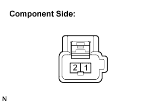
Disconnect the A22 clutch start switch connector.
Measure the resistance between the terminals.
- Standard resistance:
Tester Connection
| Switch Condition
| Specified Condition
|
1 - 2
| Clutch pedal released
| 10 kΩ or higher
|
1 - 2
| Clutch pedal depressed
| Below 1 Ω
|
Reconnect the clutch start switch connector.
| 6.REPLACE CLUTCH START SWITCH ASSEMBLY |
| 7.READ VALUE USING INTELLIGENT TESTER (STARTER SIGNAL) |
Connect the intelligent tester to the DLC3.
Turn the ignition switch to the ON position and turn the tester on.
Select the following menu items: Powertrain / Engine and ECT / Data List / Starter Signal.
Read the value displayed on the tester when the ignition switch is in the ON and START positions.
- OK:
Ignition Switch Position
| STARTER SIG
|
ON
| OFF
|
START
| ON
|
| 8.INSPECT IGNITION SWITCH ASSEMBLY |
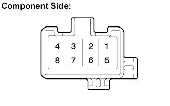
Disconnect the E23 ignition switch connector.
Measure the resistance between the terminals.
- Standard resistance:
Tester Connection
| Ignition Switch Position
| Specified Condition
|
All Terminals
| LOCK
| 10 kΩ or higher
|
2 - 4
| ACC
| Below 1 Ω
|
1 - 2 - 4, 5 - 6
| ON
|
1 - 3 - 4, 5 - 6 - 7
| START
|
Reconnect the ignition switch connector.
| 9.REPLACE IGNITION SWITCH ASSEMBLY |
| 10.READ VALUE USING INTELLIGENT TESTER (STARTER SIGNAL) |
Connect the intelligent tester to the DLC3.
Turn the ignition switch to the ON position and turn the tester on.
Select the following menu items: Powertrain / Engine and ECT / Data List / Starter Signal.
Read the value displayed on the tester when the ignition switch is in the ON and START positions.
- OK:
Ignition Switch Position
| STARTER SIG
|
ON
| OFF
|
START
| ON
|
| 11.REPAIR OR REPLACE HARNESS OR CONNECTOR (PNP SWITCH OR CLUTCH START SWITCH - STA TERMINAL OF ECM) |
| 12.CHECK WHETHER DTC OUTPUT RECURS |
Connect the intelligent tester to the DLC3.
Turn the ignition switch to the ON position.
Turn the tester on.
Clear the DTCs (CAMRY_ACV40 RM000000PDK01RX.html).
Drive the vehicle at more than 20 km/h (12.43 mph) for over 20 seconds.
Select the following menu items: Powertrain / Engine and ECT / DTC.
Read the DTCs.
- Result:
Display (DTC Output)
| Proceed To
|
P0617
| A
|
No DTC
| B
|