READ VALUE USING INTELLIGENT TESTER (ACCELERATOR POSITION SENSOR)
CHECK HARNESS AND CONNECTOR (ACCELERATOR PEDAL POSITION SENSOR - ECM)
INSPECT ECM (VCPA AND VCP2 VOLTAGE)
REPLACE ACCELERATOR PEDAL SENSOR ASSEMBLY (ACCELERATOR PEDAL POSITION SENSOR)
CHECK WHETHER DTC OUTPUT RECURS (ACCELERATOR PEDAL POSITION SENSOR DTCS)
DTC P2120 Throttle / Pedal Position Sensor / Switch "D" Circuit |
DTC P2122 Throttle / Pedal Position Sensor / Switch "D" Circuit Low Input |
DTC P2123 Throttle / Pedal Position Sensor / Switch "D" Circuit High Input |
DTC P2125 Throttle / Pedal Position Sensor / Switch "E" Circuit |
DTC P2127 Throttle / Pedal Position Sensor / Switch "E" Circuit Low Input |
DTC P2128 Throttle / Pedal Position Sensor / Switch "E" Circuit High Input |
DTC P2138 Throttle / Pedal Position Sensor / Switch "D" / "E" Voltage Correlation |
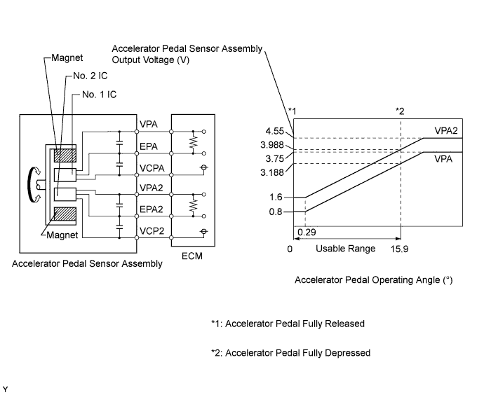
DESCRIPTION
- HINT:
- This electronic throttle control system does not use a throttle cable.
- These DTCs relate to the accelerator pedal position sensor.
The ECM monitors the actual accelerator pedal opening angle (throttle valve opening angle) through the signals from VPA and VPA2, and controls the throttle actuator according to these signals.
| DTC No. | DTC Detection Condition | Trouble Area |
| P2120 | VPA fluctuates rapidly beyond upper and lower malfunction thresholds for 0.5 seconds or more (1 trip detection logic) |
|
| P2122 | VPA is 0.4 V or less for 0.5 seconds or more when accelerator pedal depressed (1 trip detection logic) |
|
| P2123 | VPA is 4.8 V or more for 2.0 seconds or more (1 trip detection logic) |
|
| P2125 | VPA2 fluctuates rapidly beyond upper and lower malfunction thresholds for 0.5 seconds or more (1 trip detection logic) |
|
| P2127 | VPA2 is 1.2 V or less for 0.5 seconds or more when accelerator pedal is fully released (1 trip detection logic) |
|
| P2128 | Conditions (a) and (b) continue for 2.0 seconds or more (1 trip detection logic): (a) VPA2 is 4.8 V or more (b) VPA is between 0.4 V and 3.45 V |
|
| P2138 | Condition (a) or (b) continues for 2.0 seconds or more (1 trip detection logic): (a) Difference between VPA and VPA2 is 0.02 V or less (b) VPA is 0.4 V or less and VPA2 is 1.2 V or less |
|
- HINT:
- When any of these DTCs are set, check the accelerator pedal position sensor voltage by entering the following menus using the intelligent tester: Powertrain / Engine and ECT / Data List / All Data / Accel Sensor Out No.1 and Accel Sensor Out No.2.
| Trouble Area | Accel Sensor Out No. 1 When Accelerator Pedal Released | Accel Sensor Out No. 2 When Accelerator Pedal Released | Accel Sensor Out No. 1 When Accelerator Pedal Fully Depressed | Accel Sensor Out No. 2 When Accelerator Pedal Fully Depressed |
| VCP circuit open | 0 to 0.2 V | 0 to 0.2 V | 0 to 0.2 V | 0 to 0.2 V |
| Open or ground short in VPA circuit | 0 to 0.2 V | 1.2 to 2.0 V | 0 to 0.2 V | 3.4 to 5.0 V |
| Open or ground short in VPA2 circuit | 0.5 to 1.1 V | 0 to 0.2 V | 2.5 to 4.5 V | 0 to 0.2 V |
| EPA circuit open | 4.5 to 5.0 V | 4.5 to 5.0 V | 4.5 to 5.0 V | 4.5 to 5.0 V |
| Normal condition | 0.5 to 1.1 V | 1.2 to 2.0 V | 2.6 to 4.5 V | 3.4 to 5.0 V |
- HINT:
- Accelerator pedal positions are expressed as voltages.
FAIL-SAFE
When any of DTCs P2120, P2121, P2122, P2123, P2125, P2127, P2128 and P2138 are set, the ECM enters fail-safe mode. If either of the 2 sensor circuits malfunctions, the ECM uses the remaining circuit to calculate the accelerator pedal position to allow the vehicle to continue driving. If both of the circuits malfunction, the ECM regards the accelerator pedal as being released. As a result, the throttle valve is closed and the engine idles.Fail-safe mode continues until a pass condition is detected, and the ignition switch is then turned off.
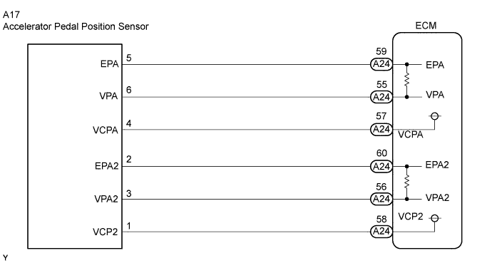
WIRING DIAGRAM
INSPECTION PROCEDURE
- HINT:
- These DTCs relate to the accelerator pedal position sensor.
- Read freeze frame data using the intelligent tester. The ECM records vehicle and driving condition information as freeze frame data the moment a DTC is stored. When troubleshooting, freeze frame data can be helpful in determining whether the vehicle was running or stopped, whether the engine was warmed up or not, whether the air fuel ratio was lean or rich, as well as other data recorded at the time of a malfunction.
| 1.READ VALUE USING INTELLIGENT TESTER (ACCELERATOR POSITION SENSOR) |
 |
Connect the intelligent tester to the DLC3.
Turn the ignition switch to ON.
Turn the tester on.
Enter the following menus: Powertrain / Engine and ECT / Data List / All Data / Accel Sensor Out No. 1 and Accel Sensor Out No. 2.
Read the values displayed on the tester.
- Standard Voltage:
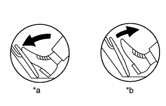
Accelerator Pedal Operation Accel Sensor Out No. 1 Accel Sensor Out No. 2 Difference between Accel Sensor Out No. 1 and Accel Sensor Out No. 2 Released 0.5 to 1.1 V 1.2 to 2.0 V More than 0.02V Fully Depressed 2.6 to 4.5 V 3.4 to 5.0 V
Text in Illustration *a Depressed *b Released
|
| ||||
|
| ||||
| 2.CHECK HARNESS AND CONNECTOR (ACCELERATOR PEDAL POSITION SENSOR - ECM) |
Disconnect the accelerator pedal sensor assembly connector.
Disconnect the ECM connector.
Measure the resistance according to the value(s) in the table below.
- Standard Resistance (Check for Open):
Tester Connection Condition Specified Condition A17-6 (VPA) - A24-55 (VPA) Always Below 1 Ω A17-5 (EPA) - A24-59 (EPA) Always Below 1 Ω A17-4 (VCPA) - A24-57 (VCPA) Always Below 1 Ω A17-3 (VPA2) - A24-56 (VPA2) Always Below 1 Ω A17-2 (EPA2) - A24-60 (EPA2) Always Below 1 Ω A17-1 (VCP2) - A24-58 (VCP2) Always Below 1 Ω
- Standard Resistance (Check for Short):
Tester Connection Condition Specified Condition A17-6 (VPA) or A24-55 (VPA) - Body ground Always 10 kΩ or higher A17-5 (EPA) or A24-59 (EPA) - Body ground Always 10 kΩ or higher A17-4 (VCPA) or A24-57 (VCPA) - Body ground Always 10 kΩ or higher A17-3 (VPA2) or A24-56 (VPA2) - Body ground Always 10 kΩ or higher A17-2 (EPA2) or A24-60 (EPA2) - Body ground Always 10 kΩ or higher A17-1 (VCP2) or A24-58 (VCP2) - Body ground Always 10 kΩ or higher
Reconnect the accelerator pedal sensor assembly connector.
Reconnect the ECM connector.
|
| ||||
| OK | |
| 3.INSPECT ECM (VCPA AND VCP2 VOLTAGE) |
Disconnect the accelerator pedal sensor assembly connector.
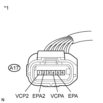 |
Turn the ignition switch to ON.
Measure the voltage according to the value(s) in the table below.
- Standard Voltage:
Tester Connection Switch Condition Specified Condition A17-4 (VCPA) - A17-5 (EPA) Ignition switch ON 4.5 to 5.5 V A17-1 (VCP2) - A17-2 (EPA2) Ignition switch ON 4.5 to 5.5 V
Text in Illustration *1 Front view of wire harness connector
(to Accelerator Pedal Sensor Assembly)
Reconnect the accelerator pedal sensor assembly connector.
|
| ||||
| OK | |
| 4.REPLACE ACCELERATOR PEDAL SENSOR ASSEMBLY (ACCELERATOR PEDAL POSITION SENSOR) |
Replace the accelerator pedal sensor assembly (CAMRY_ACV40 RM0000017UL009X.html).
| NEXT | |
| 5.CHECK WHETHER DTC OUTPUT RECURS (ACCELERATOR PEDAL POSITION SENSOR DTCS) |
Connect the intelligent tester to the DLC3.
Turn the ignition switch to ON.
Turn the tester on.
Clear the DTCs (CAMRY_ACV40 RM000000PDK0LEX.html).
Fully depress and release the accelerator pedal.
Check that 5 seconds or more have elapsed since the ignition switch was turned to ON.
Enter the following menus: Powertrain / Engine and ECT / DTC.
Read the DTCs.
- Result:
Result Proceed to DTC P2120, P2122, P2123, P2125, P2127, P2128, and/or P2138 is output A DTC is not output B
|
| ||||
| A | ||
| ||