1. REMOVE ENGINE ASSEMBLY
-
Remove the engine assembly.
2. REMOVE IGNITION COIL ASSEMBLY
-
Disconnect the 6 ignition coil connectors.

-
Remove the 6 bolts and 6 ignition coils.
3. REMOVE SPARK PLUG
-
Remove the 6 spark plugs.
4. REMOVE VVT SENSOR (for Bank 1)

-
Disconnect the sensor connector.
-
Remove the bolt and sensor.
5. REMOVE VVT SENSOR (for Bank 2)

-
Disconnect the sensor connector.
-
Remove the bolt and sensor.
6. REMOVE CAMSHAFT TIMING OIL CONTROL VALVE ASSEMBLY RH

-
Disconnect the oil control valve connector.
-
Remove the bolt and oil control valve.
-
Remove the O-ring from the oil control valve.
7. REMOVE CAMSHAFT TIMING OIL CONTROL VALVE ASSEMBLY LH

-
Disconnect the oil control valve connector.
-
Remove the bolt and oil control valve.
-
Remove the O-ring from the oil control valve.
8. REMOVE CYLINDER HEAD COVER SUB-ASSEMBLY RH
-
Remove the 10 bolts, 3 seal washers, 2 nuts, cylinder head cover and gasket.
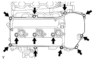
9. REMOVE CYLINDER HEAD COVER SUB-ASSEMBLY LH
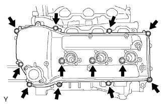
-
Remove the 10 bolts, 3 seal washers, 2 nuts, cylinder head cover and gasket.
10. REMOVE ENGINE OIL LEVEL DIPSTICK GUIDE
-
Remove the bolt and dipstick guide.
-
Remove the O-ring from the dipstick guide.
11. DISCONNECT WATER HOSE SUB-ASSEMBLY (for Automatic Transmission)
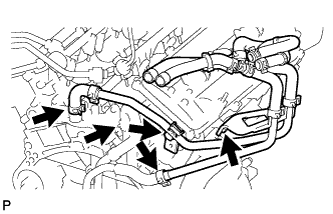
-
Remove the 2 bolts and disconnect the 3 water hoses.
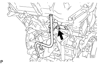
12. DISCONNECT WATER HOSE SUB-ASSEMBLY (for Manual Transmission)

-
Remove the 2 bolts and disconnect the 2 water hoses.
13. REMOVE REAR WATER BY-PASS JOINT
-
Disconnect the engine coolant temperature sensor connector.

-
Remove the 2 bolts, 4 nuts, rear water by-pass joint and 2 gaskets.

-
Remove the O-ring from the No. 1 water outlet pipe.
14. REMOVE OIL CONTROL VALVE FILTER
-
Remove the 2 unions, 2 filters and 2 gaskets from the cylinder head LH and RH.
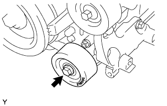
15. REMOVE V-RIBBED BELT TENSIONER ASSEMBLY

-
Remove the 5 bolts and V-ribbed belt tensioner.
16. REMOVE NO. 2 IDLER PULLEY SUB-ASSEMBLY
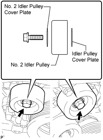
-
w/ Pulley Cover Plate: Remove the 2 bolts, 2 No. 2 idler pulley cover plate, 2 idler pulley and 2 idler pulley cover plate.

-
w/o Pulley Cover Plate: Remove the 2 bolts and 2 No. 2 idler pulleys.
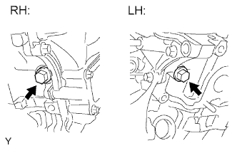
17. REMOVE NO. 1 IDLER PULLEY SUB-ASSEMBLY
-
Remove the bolt and No. 1 idler pulley.
18. REMOVE CRANKSHAFT PULLEY

-
Turn the crankshaft pulley, and align the notch with the timing mark "0" of the timing chain cover.
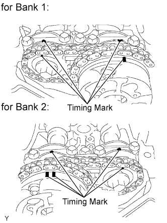
-
Check that the timing marks of the camshaft timing gears and sprockets are aligned with the timing marks of the bearing caps as shown in the illustration.

-
Using SST, hold the crankshaft pulley and loosen the pulley set bolt.
SST
09213-54015 (91651-60855) 09330-00021

-
Using the pulley set bolt and SST, remove the crankshaft pulley.
SST
09950-50013 (09951-05010,09952-05010,09953-05020,09954-05030)
19. REMOVE NO. 2 OIL PAN SUB-ASSEMBLY
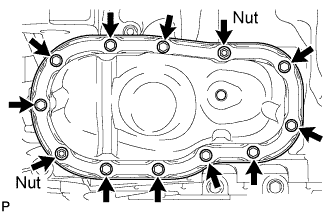
-
Remove the 10 bolts and 2 nuts.

-
Insert the blade of an oil pan seal cutter between the oil pans. Cut through the applied sealer and remove the No. 2 oil pan.
20. REMOVE OIL STRAINER SUB-ASSEMBLY

-
Remove the 2 nuts, oil strainer and gasket.
21. REMOVE OIL PAN SUB-ASSEMBLY

-
Remove the 17 bolts and 2 nuts.

-
Using a screwdriver, remove the oil pan by prying between the oil pan and cylinder block as shown in the illustration.
Text in Illustration *a Pry *b LH Side *c RH Side NOTICE:
Be careful not to damage the contact surfaces of the cylinder block and oil pan.

-
Remove the O-ring from the timing chain cover.
22. REMOVE NO. 2 OIL COOLER HOSE

-
Remove the oil cooler hose.
23. REMOVE OIL COOLER HOSE
-
Remove the oil cooler hose.
24. REMOVE WATER INLET HOUSING

-
Remove the 5 bolts and water inlet housing.
-
Remove the O-ring and gasket from the water outlet pipe and water pump.
25. REMOVE OIL FILTER BRACKET SUB-ASSEMBLY

-
Remove the 3 bolts, 2 nuts, oil filter bracket and O-ring.
26. REMOVE TIMING CHAIN COVER SUB-ASSEMBLY

-
Remove the 24 bolts labeled A and B, and the 2 nuts.

-
Remove the timing chain cover by prying between the timing chain cover and cylinder head or cylinder block with a screwdriver.
NOTICE:
Be careful not to damage the contact surfaces of the timing chain cover, cylinder block and cylinder head.
-
Remove the O-ring from the cylinder head LH side.
27. REMOVE FRONT CRANKSHAFT OIL SEAL
-
If the timing chain case is removed:
-
Using a screwdriver and wooden block, pry out the oil seal.
HINT:
Tape the screwdriver tip before use.
NOTICE:
Do not damage the surface of the oil seal press fit hole and crankshaft.
-
28. SET NO. 1 CYLINDER TO TDC/COMPRESSION
-
Turn the crankshaft pulley, and align its groove with the timing mark "0" of the timing chain cover.
-
Check that the timing marks of the camshaft timing gears and sprockets are aligned with the timing marks of the bearing caps as shown in the illustration. If not, turn the crankshaft 1 complete revolution (360°) and align the timing marks as above.
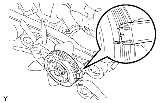
29. REMOVE NO. 1 CHAIN TENSIONER ASSEMBLY
NOTICE:
- Never rotate the crankshaft with the chain tensioner removed.
- When rotating the camshaft with the timing chain removed, rotate the crankshaft counterclockwise 40° from the TDC first.

-
While turning the stopper plate of the tensioner clockwise, push in the plunger of the chain tensioner as shown in the illustration.
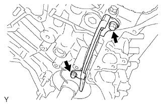
-
While turning the stopper plate of the tensioner counterclockwise, insert a bar of ?3.5 mm (0.138 in.) into the holes on the stopper plate and tensioner to fix the stopper plate in place.
-
Remove the 2 bolts and chain tensioner.
30. REMOVE CHAIN TENSIONER SLIPPER
-
Remove the chain tensioner slipper.
31. REMOVE NO. 1 IDLE GEAR SHAFT

-
Using a 10 mm hexagon wrench, remove the No. 2 idle gear shaft, No. 1 idle gear and No. 1 idle gear shaft.
32. REMOVE NO. 2 CHAIN VIBRATION DAMPER

-
Remove the 2 No. 2 chain vibration dampers.
33. REMOVE NO. 1 CHAIN SUB-ASSEMBLY
-
Remove the No. 1 chain.
34. REMOVE NO. 1 CHAIN VIBRATION DAMPER
-
Remove the 2 bolts and No. 1 chain vibration damper.
35. REMOVE CAMSHAFT TIMING GEARS AND NO. 2 CHAIN
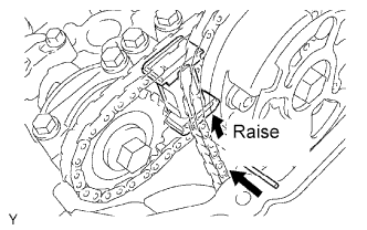
-
While raising the No. 2 chain tensioner, insert a pin of ?1.0 mm (0.0394 in.) into the hole to fix the tensioner in place.

-
Hold the hexagonal portion of the camshaft with a wrench, and remove the 2 bolts, camshaft timing gear, camshaft timing sprocket and No. 2 chain.
NOTICE:
- Be careful not to damage the cylinder head and valve lifter with the wrench.
- Do not disassemble the camshaft timing gear.
36. REMOVE NO. 2 CHAIN TENSIONER ASSEMBLY

-
Remove the bolt and No. 2 chain tensioner.
37. REMOVE NO. 1 CAMSHAFT AND NO. 2 CAMSHAFT
NOTICE:
As the thrust clearance of the camshaft is small, the camshaft must be kept level while it is being removed. If the camshaft is not kept level, the portion of the cylinder head which receives the shaft thrust may crack or be damaged, causing the camshaft to seize or break. To avoid this, the following steps should be carried out.

-
Rotate the camshafts counterclockwise using a wrench so that the cam lobes of the No. 1 cylinder face each direction as shown in the illustration.
-
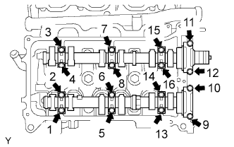
Uniformly loosen and remove the 16 bearing cap bolts in the sequence shown in the illustration.
-
Remove the 8 bearing caps and 2 camshafts.
38. REMOVE CYLINDER HEAD SUB-ASSEMBLY RH

-
Using a 10 mm bi-hexagon wrench, uniformly loosen the 8 cylinder head bolts in the sequence shown in the illustration. Remove the 8 cylinder head bolts and plate washers.
NOTICE:
- Be careful not to drop the plate washers into the cylinder head.
- Cylinder head warpage or cracking could result from removing bolts in the incorrect order.

-
Lift the cylinder head from the dowels on the cylinder block, and place the cylinder head on wooden blocks on a bench.
NOTICE:
Be careful not to damage the contact surfaces of the cylinder head and cylinder block.
HINT:
If the cylinder head is difficult to lift off, pry between the cylinder head and cylinder block with a screwdriver.
39. REMOVE NO. 1 CAMSHAFT BEARING

40. REMOVE NO. 2 CAMSHAFT BEARING

41. REMOVE CYLINDER HEAD GASKET
42. REMOVE NO. 3 CHAIN TENSIONER ASSEMBLY

-
Remove the bolt and No. 3 chain tensioner.
43. REMOVE NO. 3 CAMSHAFT AND NO. 4 CAMSHAFT
NOTICE:
As the thrust clearance of the camshaft is small, the camshaft must be kept level while it is being removed. If the camshaft is not kept level, the portion of the cylinder head which receives the shaft thrust may crack or be damaged, causing the camshaft to seize or break. To avoid this, the following steps should be carried out.

-
Uniformly loosen and remove the 16 bearing cap bolts in the sequence shown in the illustration.
-
Remove the 8 bearing caps and 2 camshafts.
44. REMOVE CYLINDER HEAD SUB-ASSEMBLY LH

-
Uniformly loosen and remove the 2 cylinder head bolts in the sequence shown in the illustration.

-
Using a 10 mm bi-hexagon wrench, uniformly loosen the 8 cylinder head bolts in the sequence shown in the illustration. Remove the 8 cylinder head bolts and plate washers.
NOTICE:
- Be careful not to drop the plate washers into the cylinder head.
- Cylinder head warpage or cracking could result from removing bolts in the incorrect order.

-
Lift the cylinder head from the dowels on the cylinder block, and place the cylinder head on wooden blocks on a bench.
NOTICE:
Be careful not to damage the contact surfaces of the cylinder head and cylinder block.
HINT:
If the cylinder head is difficult to lift off, pry between the cylinder head and cylinder block with a screwdriver.
45. REMOVE NO. 2 CYLINDER HEAD GASKET