-
Remove the 3 bolts and screw.
-
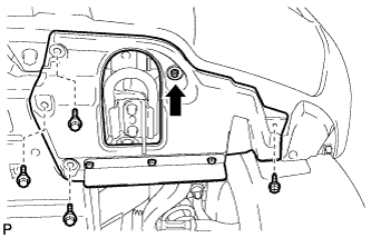
Turn the clip indicated by the arrow in the illustration to remove the fender splash shield.
HINT:
Use the same procedures described for the LH side.
-
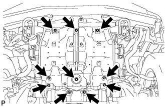
Remove the 10 bolts and under cover.
-
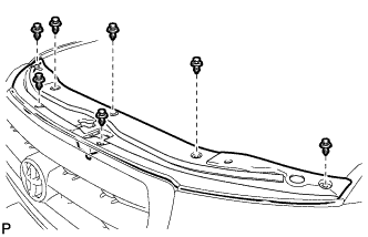
Remove the 7 clips and radiator support seal.
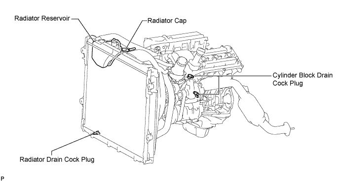
CAUTION:
Do not remove the radiator cap while the engine and radiator are still hot. Pressurized, hot engine coolant and steam may be released and cause serious burns.
-
Loosen the radiator drain cock plug and 2 cylinder block drain cock plugs.
-
Remove the radiator cap. Then drain the coolant.
HINT:
Collect the coolant in a container and dispose of it according to the regulations in your area.
-
Tighten the 2 cylinder block drain cock plugs.
Torque:
13 N*m{ 133 kgf*cm , 10 ft.*lbf }
-
Tighten the radiator drain cock plug by hand.
-
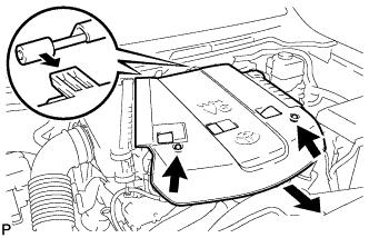
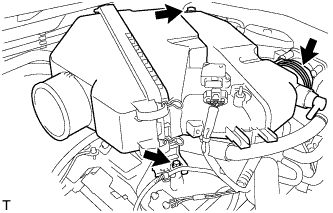
Remove the 2 cap nuts and V-bank cover.
-
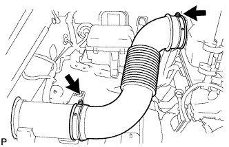
Loosen the 2 hose clamps and remove the air cleaner hose.
-
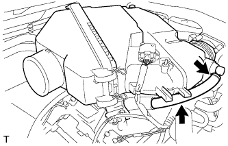
Disconnect the No. 2 ventilation hose.
-
Detach the hose clamp.
-
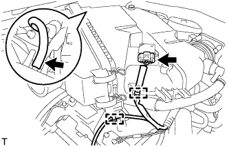
Disconnect the vacuum hose.
-
Disconnect the MAF meter connector.
-
Using a clip remover, detach the 2 wire harness clamps.
-
Loosen the hose clamp.
-
Remove the 2 bolts and air cleaner assembly.
-
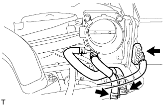
Disconnect the throttle body connector.
-
Disconnect the No. 4 water by-pass hose.
-
Disconnect the No. 5 water by-pass hose.
-
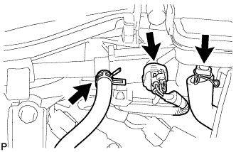
Disconnect the purge line hose.
-
Disconnect the purge VSV connector.
-
Disconnect the No. 1 ventilation hose.
-
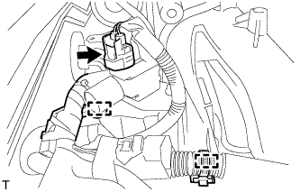
Disconnect the vacuum switching valve (for ACIS) connector.
-
Using a clip remover, detach the 2 wire harness clamps.
-
Remove the 2 bolts and throttle body bracket.
-
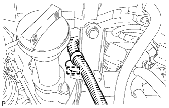
Using a clip remover, detach the wire harness clamp.
-
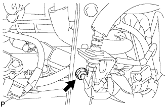
Remove the bolt and bracket from the No. 1 surge tank stay.
-
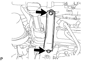
Remove the bolt and oil baffle plate.
-
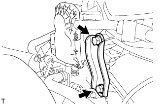
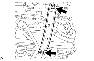
Remove the 2 bolts and No. 1 surge tank stay.
-
for Manual Transmission:
-
Remove the nut.
-
-
Remove the 2 bolts and No. 2 surge tank stay.
-
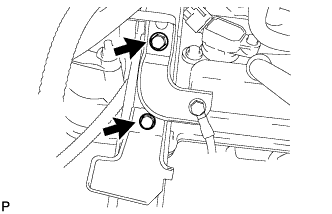
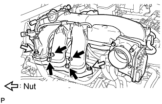
Remove the 2 nuts.
-
Using an 8 mm hexagon wrench, remove the 4 bolts. Then remove the intake air surge tank and gasket.
-
Disconnect the 6 connectors.
-
Remove the 6 bolts and ignition coils.
-
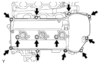
Remove the 10 bolts, 3 seal washers, 2 nuts, cylinder head cover and gasket.
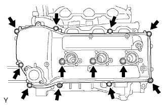
-
Remove the 10 bolts, 3 seal washers, 2 nuts, cylinder head cover and gasket.
-
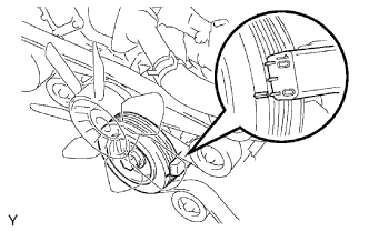
Turn the crankshaft pulley, and align its groove with the timing mark "0" of the timing chain cover.
-
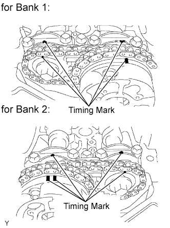
Check that the timing marks of the camshaft timing gears and sprockets are aligned with the timing marks of the bearing caps as shown in the illustration. If not, turn the crankshaft 1 complete revolution (360°) and align the timing marks as above.
NOTICE:
- Never rotate the crankshaft with the chain tensioner removed.
- When rotating the camshaft with the timing chain removed, rotate the crankshaft counterclockwise 40° from TDC first.
-
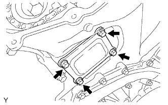
Remove the 4 bolts, timing chain cover plate and gasket.
-
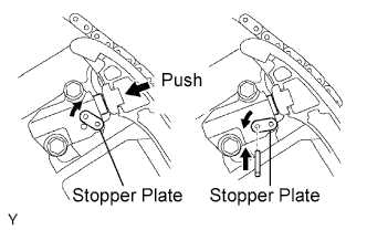
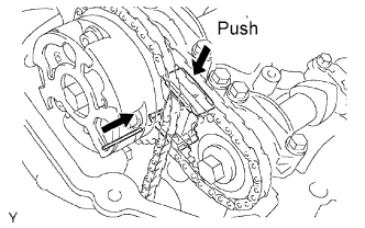
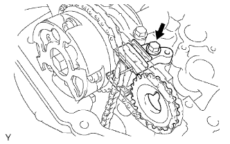
While turning the stopper plate of the tensioner clockwise, push in the plunger of the chain tensioner as shown in the illustration.
-
While turning the stopper plate of the tensioner counterclockwise, insert a bar of ?3.5 mm (0.138 in.) into the holes on the stopper plate and tensioner to fix the stopper plate in place.
-
Remove the 2 bolts and chain tensioner.
NOTICE:
As the thrust clearance of the camshaft is small, the camshaft must be kept level while it is being removed. If the camshaft is not kept level, the portion of the cylinder head which receives the shaft thrust may crack or be damaged, causing the camshaft to seize or break. To avoid this, the following steps should be carried out.

-
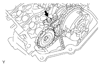
While raising the No. 2 chain tensioner, insert a pin of ?1.0 mm (0.0394 in.) into the hole to fix the tensioner in place.
-
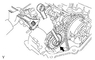
Hold the hexagonal portion of the No. 2 camshaft with a wrench, and remove the camshaft timing sprocket set bolt.
NOTICE:
Be careful not to damage the cylinder head and valve lifter with the wrench.
-
Separate the camshaft timing sprocket from the No. 2 camshaft.
-
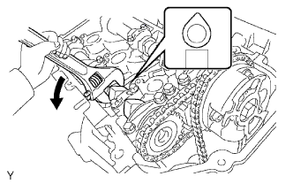
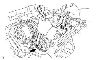
Rotate the camshaft counterclockwise using a wrench so that the cam lobes of the No. 1 cylinder face upward as shown in the illustration.

-
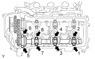
Using several steps, loosen and remove the 8 bearing cap bolts uniformly in the sequence shown in the illustration.
-
Remove the 4 bearing caps and No. 2 camshaft.
-
Remove the No. 2 chain tensioner bolt, and then remove the No. 2 chain tensioner and camshaft timing sprocket.
NOTICE:
As the thrust clearance of the camshaft is small, the camshaft must be kept level while it is being removed. If the camshaft is not kept level, the portion of the cylinder head which receives the shaft thrust may crack or be damaged, causing the camshaft to seize or break. To avoid this, the following steps should be carried out.
-
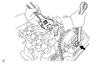
Hold the hexagonal portion of the No. 1 camshaft with a wrench, and loosen the camshaft timing gear set bolt.
NOTICE:
- Be careful not to damage the cylinder head and valve lifter with the wrench.
- Do not disassemble the camshaft timing gear assembly.
-
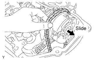
Slide the camshaft timing gear and separate the No. 1 chain from the camshaft timing gear.
-
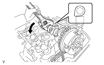
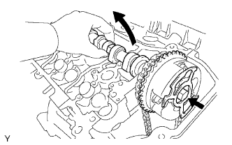
Rotate the No. 1 camshaft counterclockwise using a wrench so that the cam lobes of the No. 1 cylinder face downward as shown in the illustration.
-
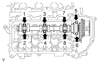
Using several steps, loosen and remove the 8 bearing cap bolts in the sequence shown in the illustration.
-
Remove the 4 bearing caps.
-
Remove the camshaft timing gear set bolt with the No. 1 camshaft lifted up, and then remove the No. 1 camshaft and camshaft timing gear with the No. 2 chain.
-
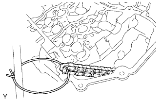
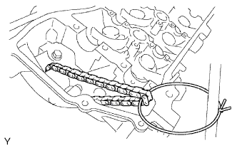
Tie the No. 1 chain with a string as shown in the illustration.
NOTICE:
Be careful not to drop anything inside the timing chain cover.
NOTICE:
As the thrust clearance of the camshaft is small, the camshaft must be kept level while it is being removed. If the camshaft is not kept level, the portion of the cylinder head which receives the shaft thrust may crack or be damaged, causing the camshaft to seize or break. To avoid this, the following steps should be carried out.
-
While pushing down the No. 3 chain tensioner, insert a pin of ?1.0 mm (0.0394 in.) into the hole to fix the tensioner in place.
-
Hold the hexagonal portion of the No. 4 camshaft with a wrench, and remove the camshaft timing sprocket set bolt.
NOTICE:
Be careful not to damage the cylinder head and valve lifter with the wrench.
-
Separate the camshaft timing sprocket from the No. 4 camshaft.
-
Using several steps, loosen and remove the 8 bearing cap bolts uniformly in the sequence shown in the illustration.
-
Remove the 4 bearing caps and No. 4 camshaft.
-
Remove the No. 3 chain tensioner bolt, and then remove the No. 3 chain tensioner and camshaft timing sprocket.
NOTICE:
As the thrust clearance of the camshaft is small, the camshaft must be kept level while it is being removed. If the camshaft is not kept level, the portion of the cylinder head which receives the shaft thrust may crack or be damaged, causing the camshaft to seize or break. To avoid this, the following steps should be carried out.

-
Release the chain tension between the camshaft timing gear (LH bank) and crankshaft timing gear by turning the crankshaft pulley counterclockwise slightly.

-
Hold the hexagonal portion of the No. 3 camshaft with a wrench, and loosen the camshaft timing gear set bolt.
NOTICE:
- Be careful not to damage the cylinder head and valve lifter with the wrench.
- Do not disassemble the camshaft timing gear assembly.

-
Slide the camshaft timing gear and separate the No. 1 chain from the camshaft timing gear.

-
Using several steps, loosen and remove the 8 bearing cap bolts uniformly in the sequence shown in the illustration.
-
Remove the 4 bearing caps.

-
Remove the camshaft timing gear set bolt with the No. 3 camshaft lifted up, and then remove the No. 3 camshaft and camshaft timing gear with the No. 2 chain.
-
Tie the No. 1 chain with a string as shown in the illustration.
NOTICE:
Be careful not to drop anything inside the timing chain cover.